Centrifugal pump impeller

A centrifugal pump impeller and impeller technology, applied to pumps, pump components, non-variable pumps, etc., can solve problems such as difficult welding and slow water flow, and achieve the effects of improving connection strength, facilitating welding, and reducing the impact of flow velocity

Pending Publication Date: 2018-09-21
ZHEJIANG NANYUAN PUMP IND CO LTD
View PDF0 Cites 0 Cited by
  • Summary
  • Abstract
  • Description
  • Claims
  • Application Information

AI Technical Summary

Problems solved by technology

[0003] The purpose of the present invention is to address the above problems and provide a centrifugal pump impeller with a reasonable design that solves the problems of difficult welding and slowing down of water flow caused by welding scars.

Method used


Image

  • Centrifugal pump impeller
  • Centrifugal pump impeller
  • Centrifugal pump impeller

Examples


Embodiment Construction

[0023] The present invention will be further described in detail below in conjunction with the accompanying drawings and examples. The following examples are explanations of the present invention and the present invention is not limited to the following examples.

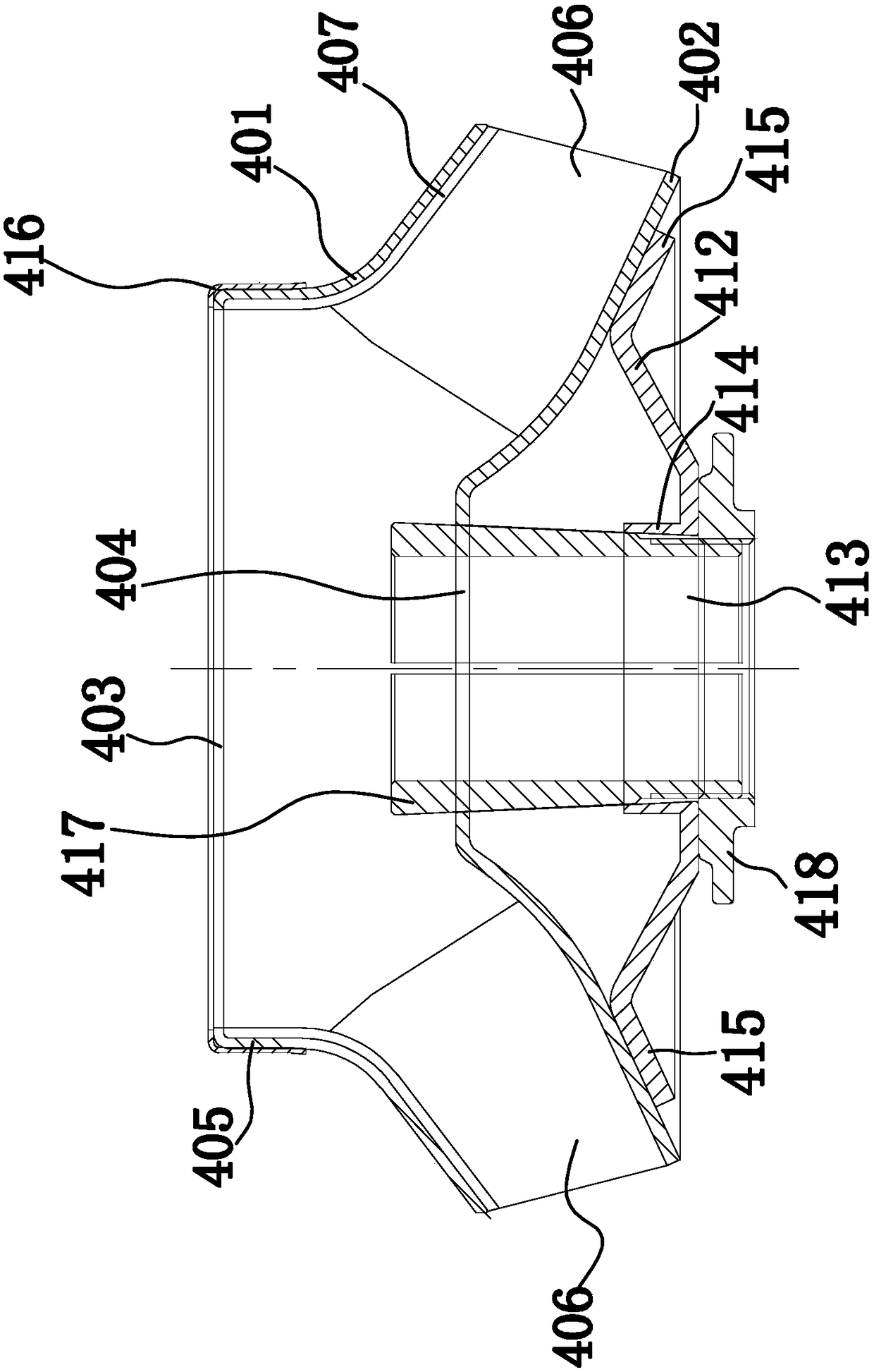
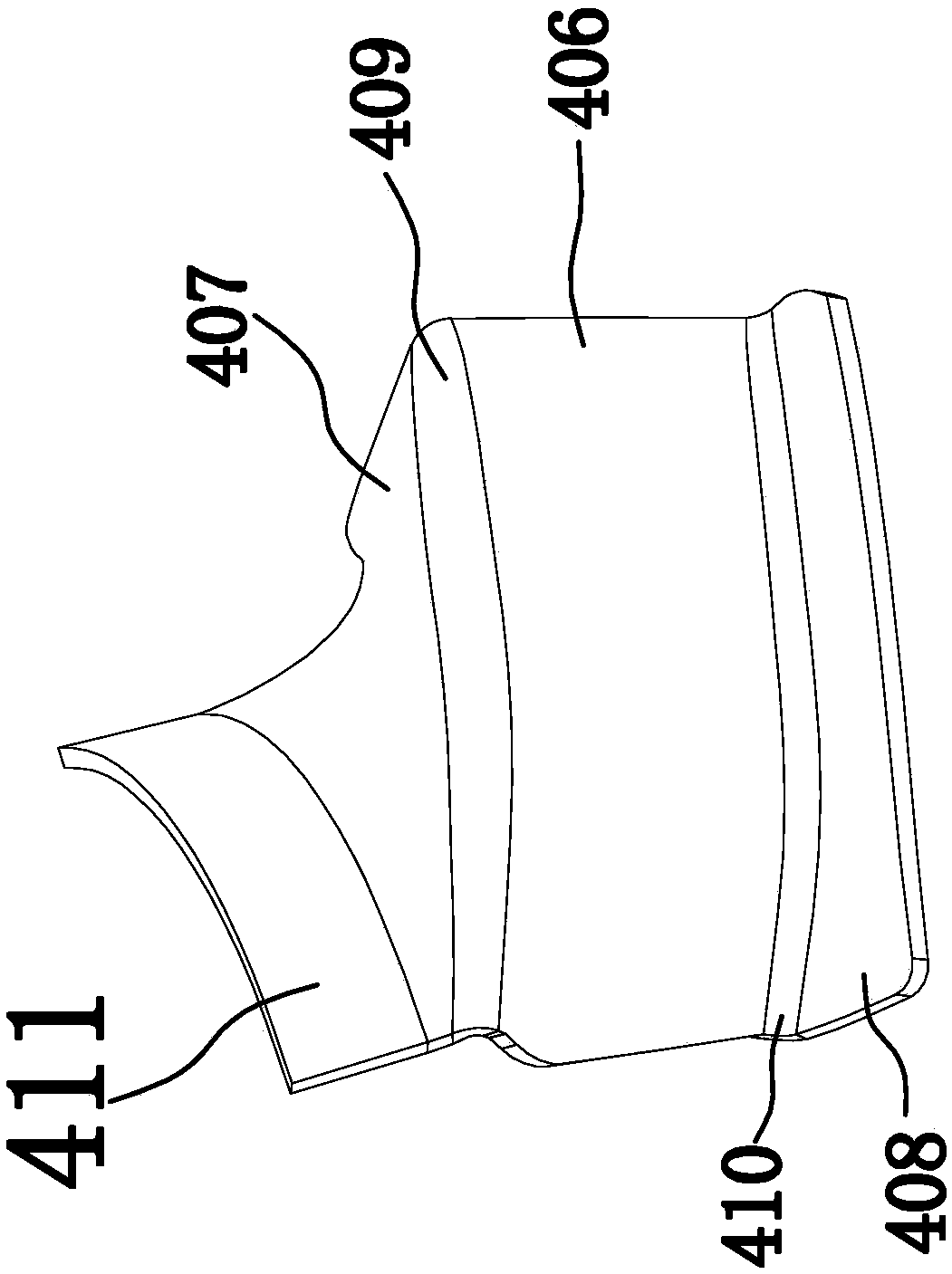
[0024] Such as Figures 1 to 6 As shown, the impeller of the centrifugal pump includes a first impeller cover plate 401 and a second impeller cover plate 402 arranged in sequence along the same axial direction. An impeller through hole 403, the middle part of the second impeller cover plate 402 is provided with a second impeller through hole 404 for the external pump shaft 101 to pass through, between the first impeller cover plate 401 and the second impeller cover plate 402 there is a The coaxial impeller fixing member for fixing the impeller on the pump shaft 101 and keeping the impeller and the pump shaft 101 rotating synchronously is characterized in that: the first impeller cover plate 401 is located in the fir...


PUM


Abstract

The invention provides a centrifugal pump impeller, belongs to the technical field of production of liquid pump equipment and solves the problems such as unreasonable design of the prior art. The centrifugal pump impeller comprises a first impeller cover plate and a second impeller cover plate which are successively arranged along the same axial direction; a first impeller through hole for passingof an outer pump shaft is formed in the middle of the first impeller cover plate; a second impeller through hole for passing of the outer pump shaft is formed in the middle of the second impeller cover plate. The centrifugal pump impeller has the advantages that a first impeller extension vane and a second impeller extension vane are arranged on each impeller vane, the welding of the impeller vanes with the first impeller cover plate and the second impeller cover plate is facilitated, the connection strength is improved, the first impeller extension vanes and the second impeller extension vanes are connected with the impeller vanes to form a whole body, and the influence on the flowing speed of the water flow is reduced.

Description

technical field [0001] The invention belongs to the technical field of liquid pump equipment manufacture, and in particular relates to a centrifugal pump impeller. Background technique [0002] A liquid centrifugal pump is a pump that transports liquid by the centrifugal force generated when the impeller rotates. The blades of the impellers in the existing liquid centrifugal pumps are only welded to the cover plate of the impeller with a very narrow side, which has low connection strength and high requirements for welding, and the welding scars left during welding will slow down the flow rate of the water flow and other defects. Contents of the invention [0003] The object of the present invention is to solve the above problems and provide a centrifugal pump impeller with reasonable design, which solves the problems of difficult welding and slowing down of water flow caused by welding scars. [0004] In order to achieve the above object, the present invention adopts the...

Claims


Application Information

Patent Timeline
Patent Type & Authority Applications(China)
IPC IPC(8): F04D29/24F04D29/22F04D29/66
CPCF04D29/2222F04D29/24F04D29/669
Inventor 姚松保石绿瑞金记明
Owner ZHEJIANG NANYUAN PUMP IND CO LTD
Why Eureka
Try Eureka