
Heat exchanger and heat exchange apparatus

A heat exchange equipment, heat exchanger technology, applied in the direction of heat exchanger shell, indirect heat exchanger, heat exchange equipment, etc., can solve the problems of small heat exchange area between heat exchange tubes and fins, large thermal resistance, etc. It is not easy to leak refrigerant, increase the heat exchange area, and ensure the reliability and safety.

Inactive Publication Date: 2018-09-21
GD MIDEA AIR-CONDITIONING EQUIP CO LTD +1
View PDF11 Cites 6 Cited by
  • Summary
  • Abstract
  • Description
  • Claims
  • Application Information

AI Technical Summary

Problems solved by technology

[0003] The main purpose of the present invention is to provide a heat exchanger, aiming to solve the problem of small heat exchange area and large thermal resistance of heat exchange tubes and fins in the prior art

Method used


Image

  • Heat exchanger and heat exchange apparatus
  • Heat exchanger and heat exchange apparatus
  • Heat exchanger and heat exchange apparatus

Examples


Embodiment Construction

[0046] The following will clearly and completely describe the technical solutions in the embodiments of the present invention with reference to the accompanying drawings in the embodiments of the present invention. Obviously, the described embodiments are only some of the embodiments of the present invention, not all of them. Based on the embodiments of the present invention, all other embodiments obtained by persons of ordinary skill in the art without creative efforts fall within the protection scope of the present invention.

[0047] It should be noted that all directional indications (such as up, down, left, right, front, back...) in the embodiments of the present invention are only used to explain the relationship between the components in a certain posture (as shown in the accompanying drawings). Relative positional relationship, movement conditions, etc., if the specific posture changes, the directional indication will also change accordingly.

[0048] In addition, the ...


PUM


Abstract

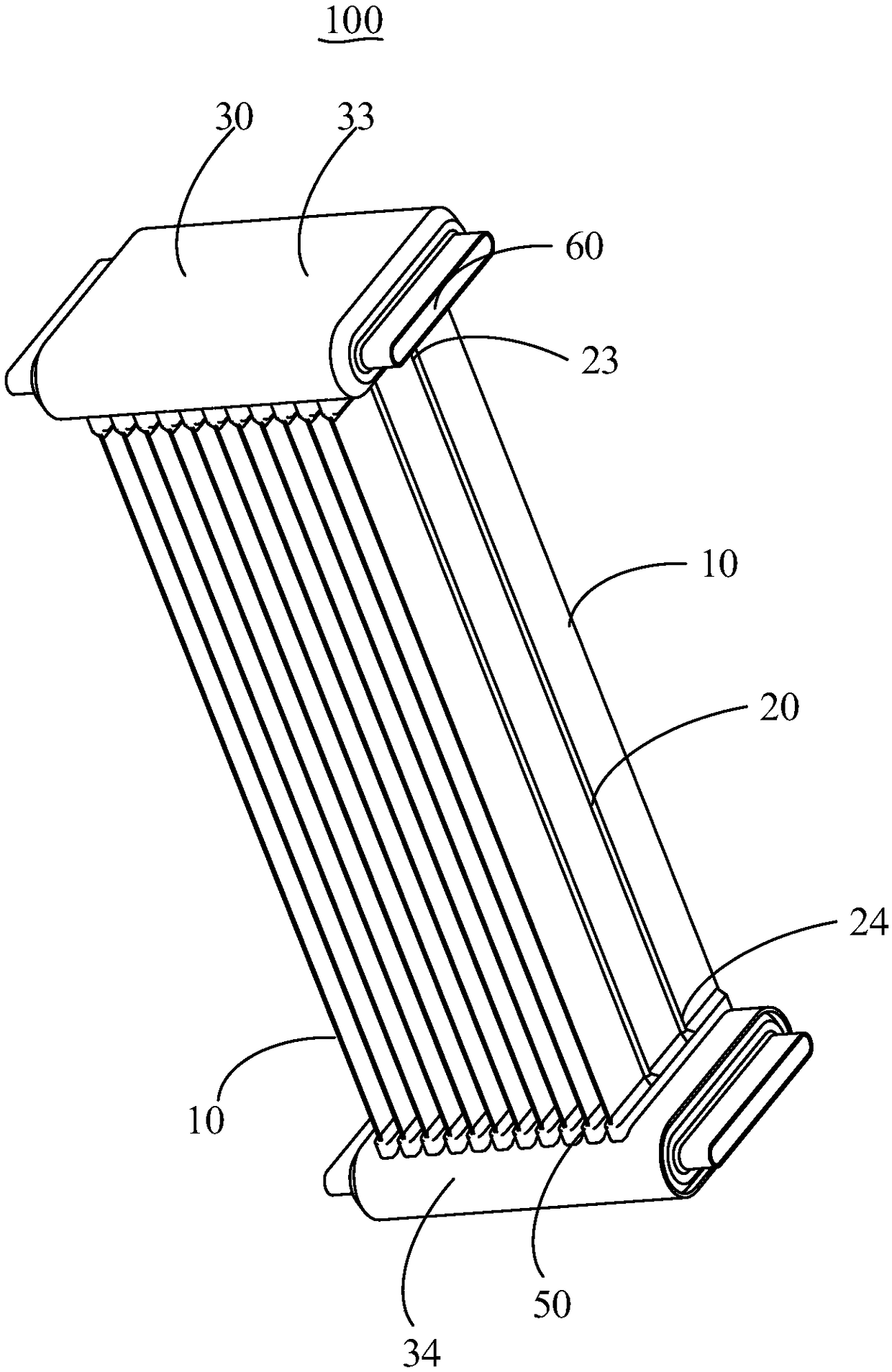
The invention provides a heat exchanger and a heat exchange apparatus. The heat exchanger comprises: a plurality of fins that are arranged at intervals; a plurality of heat exchange pipes extended onthe surface of the fins or formed in the fins. The heat exchanger and the heat exchange apparatus have the advantage the heat exchange pipes and the fins are high in heat exchange quantity and heat exchange efficiency.

Description

technical field [0001] The invention relates to the technical field of heat exchangers, in particular to a heat exchanger and heat exchange equipment. Background technique [0002] In the prior art, the heat exchange tubes of the heat exchanger are generally installed vertically in the fins, the fins are generally placed vertically, and the heat exchange tubes are generally installed horizontally in the fins, and the heat exchange tubes and the fins The heat transfer area of ​​the sheet is small and the thermal resistance is large, which leads to a decrease in the heat transfer efficiency between the heat transfer tube and the fin. Contents of the invention [0003] The main purpose of the present invention is to provide a heat exchanger aimed at solving the problems in the prior art that the heat exchange area of ​​the heat exchange tubes and the fins is small and the heat resistance is large. [0004] In order to achieve the above object, the present invention proposes ...

Claims


Application Information

Patent Timeline
Patent Type & Authority Applications(China)
IPC IPC(8): F28D1/053F28F1/02F28F1/12F28F1/22F28F9/02F28F19/02F28F21/02
CPCF28D1/05333F28F1/02F28F1/126F28F1/22F28F9/02F28F19/02F28F21/02F28F2215/04F28F2215/10F28F2275/06
Inventor 北本学何哲旺陈新厂
Owner GD MIDEA AIR-CONDITIONING EQUIP CO LTD
Learn More