Vibration total heat exchanger for enhancing heat transfer

A total heat exchanger and heat transfer technology, applied in the directions of household heating, heating methods, household heating, etc., can solve the problems of rising cost and price of heat exchangers, increased fluid pressure loss, and increased installation weight, etc. Less internal support, less wind pressure loss, and less resistance along the way

Pending Publication Date: 2021-09-17
ZHEJIANG SCI-TECH UNIV
View PDF5 Cites 0 Cited by
  • Summary
  • Abstract
  • Description
  • Claims
  • Application Information

AI Technical Summary

Problems solved by technology

[0004] The thermal resistance of the fluid thermal boundary layer limits the improvement of heat exchanger efficiency. Even in turbulent flow, a boundary layer will be generated between the fluid and the solid wall. The flow nature of the bottom layer of the fluid is laminar flow, which is conducted by molecular diffusion. Heat transfer, the heat transfer rate is very small, and its thermal resistance accounts for almost 80% of the thermal resistance of the entire boundary layer, and the thickness of the boundary layer can be thinned by increasing the fluid velocity, thereby increasing the heat transfer rate, but increasing the fluid velocity will cause A paradoxical consequence, that the pressure loss of the fluid also increases
Increasing the heat transfer area is also one of the effective ways to increase the preheating temperature and heat recovery rate, but limited by many factors, the cost and price of the heat exchanger will increase while the size and installation weight will also increase

Method used


Image

  • Vibration total heat exchanger for enhancing heat transfer
  • Vibration total heat exchanger for enhancing heat transfer
  • Vibration total heat exchanger for enhancing heat transfer

Examples


Embodiment Construction

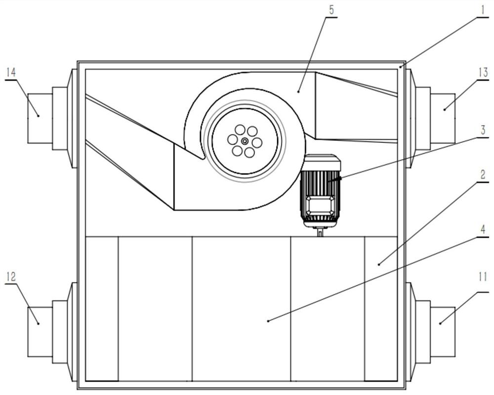
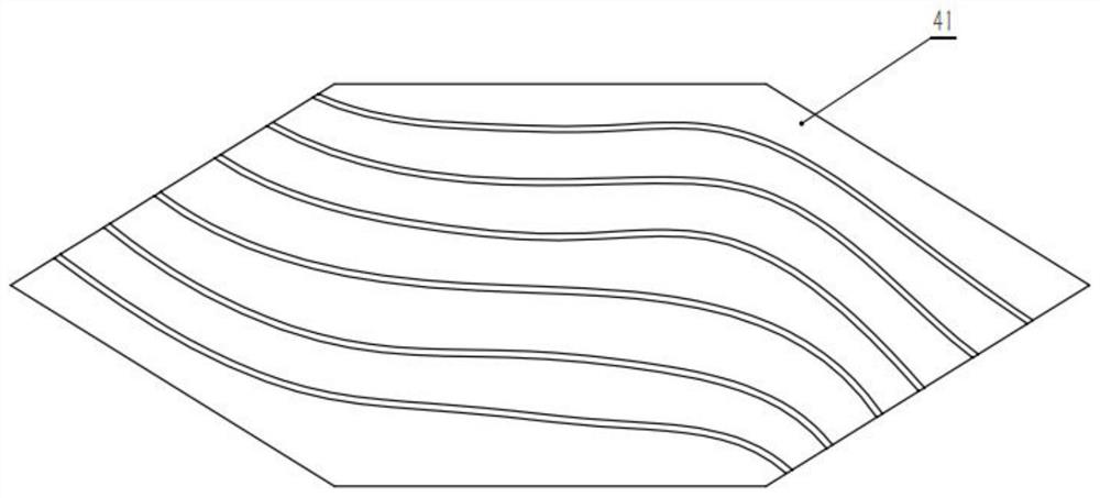
[0021] Such as Figure 1-4 As shown, a vibrating total heat exchanger that enhances heat transfer includes a noise reduction casing 1, an outdoor air inlet 11, an indoor air outlet 14, an indoor air inlet 12, an outdoor air outlet 13, a filter screen 2, and a heat exchange core 4 and a double-layer fan 5; the noise reduction casing 1 is provided with a sound insulation layer; the outdoor air inlet 11 and the indoor air outlet 14 are all located on the right side of the noise reduction casing 1, and the indoor air outlet 14 is located at the outdoor air inlet The top of the air inlet 11; the indoor air inlet 12 and the outdoor air outlet 13 are located on the left side of the noise reduction casing 1, and the outdoor air outlet 13 is located above the indoor air inlet 12; and in the present embodiment, the filter screen 2 The quantity is 1 pair, the pair of filter screens 2 are not in contact with each other, and the pair of filter screens 2 are fixedly connected to the noise r...


PUM


Abstract

The invention discloses a vibration total heat exchanger for enhancing heat transfer. The vibration total heat exchanger comprises a noise reduction machine shell, an outdoor air inlet, an indoor air outlet, an indoor air inlet, an outdoor air outlet, a pair of filter screens, a heat exchange core and a double-layer fan, wherein the outdoor air inlet and the indoor air outlet are formed in one side of the noise reduction machine shell, the indoor air inlet and the outdoor air outlet are formed in the other side of the noise reduction machine shell, the pair of filter screens are arranged on the noise reduction machine shell, the heat exchange core is arranged between the pair of filter screens, and the double-layer fan is used for connecting the indoor air outlet and the outdoor air outlet; and a heat exchange plate is arranged in the heat exchange core and is of a special-shaped structure, and corrugations are arranged on the surface of the heat exchange plate. Through the arrangement of the heat exchange plate special-shaped structure, inner supports are reduced, on-way resistance is small, wind pressure loss is small, maximization of the heat transfer area is guaranteed, and therefore the maximum heat exchange efficiency is achieved.

Description

technical field [0001] The invention belongs to the technical field of total heat exchangers, in particular to a vibrating total heat exchanger for enhancing heat transfer. Background technique [0002] Today, indoor air quality issues are increasingly concerned by people. With the improvement of the quality of life, people hope that there can be fresh air in the room even without opening the window. The air purifiers on the market can only achieve a small range of internal air purification, and cannot achieve indoor and outdoor ventilation. Therefore, the total heat exchanger came into being. The total heat exchanger is a two-way flow ventilation equipment, which discharges the indoor dirty air to the outside and at the same time introduces the outdoor fresh air into the room. Its heat exchange function can recover energy from the exhaust gas and heat and humidify the fresh air entering the room. processing to help air conditioners save energy. In summer, the heat and mo...

Claims


Application Information

Patent Timeline
Patent Type & Authority Applications(China)
IPC IPC(8): F24F7/08F24F12/00F24F13/20F24F13/24F24F13/28F24F13/30
CPCF24F7/08F24F12/006F24F13/20F24F13/30F24F13/24F24F13/28
Inventor 魏义坤童惠琳王峥宇王政道杨徽张炜
Owner ZHEJIANG SCI-TECH UNIV
Why Eureka
Try Eureka