Speckle inhibition method and device based on chaotic laser

A chaotic laser and suppression device technology, applied in optics, optical components, instruments, etc., can solve the problems of reducing laser temporal coherence and spatial coherence, and achieve low autocorrelation sidelobes, more randomness, and good randomness Effect

Pending Publication Date: 2018-09-21
TAIYUAN UNIV OF TECH
View PDF0 Cites 1 Cited by
  • Summary
  • Abstract
  • Description
  • Claims
  • Application Information

AI Technical Summary

Problems solved by technology

[0009] In order to solve the problem of reducing the temporal coherence and spatial coherence of the laser light sourc

Method used


Image

  • Speckle inhibition method and device based on chaotic laser
  • Speckle inhibition method and device based on chaotic laser

Examples


Example Embodiment

[0027] Example 1

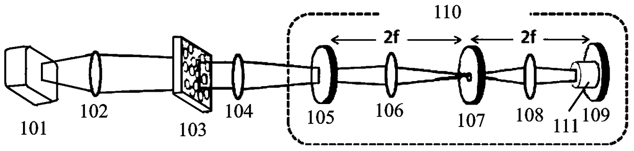
[0028] In this embodiment, the laser device 1 is a semiconductor laser device for laser display; the converging lens 2 is a high-curvature uniform converging lens with a focal length of 5 mm; the aperture of the aperture 3 is 2 mm; the focal length of the collimating lens 4 is 1.5 mm; The reflectivity of mirror 5 is 20%, and collimating lens 4 and reflective mirror 5 are closely fixed; The distance between converging lens 2 and laser 1 and the distance between diaphragm 3 and converging lens 2 are 5mm; The distance between the diaphragm 3 and the collimating lens 4 is 1.5mm; each optical element is placed coaxially.

[0029] The specific operation of this embodiment is as follows: after the laser light emitted by the laser device 1 is converged by the converging lens 2, the focus of the converging light passes through the light aperture of the diaphragm 3, then is collimated by the collimating lens 4, and is incident on the transflective mirror 5, The light...

Example Embodiment

[0030] Example 2

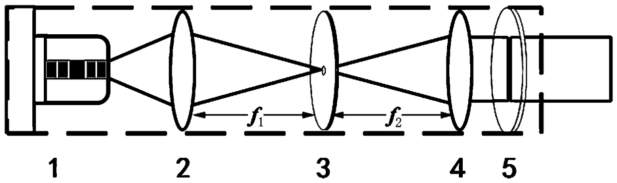
[0031] In this embodiment, the laser 1 is a semiconductor laser for laser display; the converging lens 2 is a high-curvature uniform converging lens with a focal length of 7mm; The optical aperture is 1.5mm; the focal length of the collimating lens 4 is 0.8mm; the reflectivity of the retroreflective mirror 5 is 35%, and the distance between the collimating lens 4 and the retroreflective mirror 5 is set to 10mm; between the converging lens 2 and the laser 1 The distance between the multimode fiber and the converging lens 2 is 7mm; the distance between the multimode fiber and the collimator lens 4 is 0.8mm; each optical element is placed coaxially.

[0032] The specific operation of this embodiment is as follows: after the laser light emitted by the laser device 1 is converged by the converging lens 2, the focus of the converging light passes through the light hole of the multimode optical fiber, then is collimated by the collimating lens 4, and is incident on...


PUM

PropertyMeasurementUnit
Focal lengthaaaaaaaaaa
Clear apertureaaaaaaaaaa

Abstract

The invention discloses a speckle inhibition method and device based on chaotic laser, relating to the field of light sources for laser display. The device mainly comprises a laser device, wherein a convergent lens, a diaphragm, a collimating lens and a transflective mirror are sequentially arranged on one side, on which laser is emitted, of the laser, and the distance between the convergent lensand the transflective mirror and the distance between the convergent lens and the diaphragm are the focal lengths of the convergent lens; and the distance between the diaphragm and the collimating lens is the focal length of the collimating lens, and all devices are coaxially arranged. The laser emitted by the laser device is converged by the convergent lens, the focus of converged light passes through a light transmission hole of the diaphragm, is collimated through the collimating lens and is incident into the transflective mirror, light reflected from the transflective mirror returns to thelaser device from the original road to enable the laser device to generate chaos, and emergent light is taken as a low coherence light source of a system and is directly output. According to the device, a multi-path feedback effect is achieved, and the coherence of the laser is reduced from a space domain due to the increase of the paths and is also reduced from a time domain by virtue of the chaos state.

Description

technical field [0001] The invention relates to the field of light sources for laser display, in particular to a chaotic laser-based speckle suppression device. Background technique [0002] With its advantages such as large color gamut, high color saturation, high electro-optical conversion efficiency, and long light source life, laser display technology has become the most promising new generation display technology after CRT, plasma, and LCD / LED display technologies. However, due to the extremely high temporal and spatial coherence of laser light, compound speckle exists in laser projection imaging, which seriously reduces the resolution and contrast of projected images. This problem has always been a key issue hindering the development of laser display technology. Therefore, researchers have proposed a variety of methods to suppress speckle by controlling the temporal and spatial coherence of laser light. The specific methods are mainly divided into three categories: ...

Claims


Application Information

Patent Timeline
IPC IPC(8): G02B27/48
CPCG02B27/48
Inventor 赵彤郭园园王安帮高华李青天
Owner TAIYUAN UNIV OF TECH
Why Eureka
Try Eureka