A cable load measurement device and measurement method based on finite element simulation

A technology for measuring device and cable load, applied in the direction of design optimization/simulation, special data processing application, etc., can solve the problem of not considering the influence of air and cable convection heat dissipation and contact thermal resistance, etc., to achieve the effect of convenient operation

Active Publication Date: 2022-01-11
深圳市安讯实业有限公司
View PDF8 Cites 0 Cited by
  • Summary
  • Abstract
  • Description
  • Claims
  • Application Information

AI Technical Summary

Problems solved by technology

[0005] The above-mentioned patent judges the load of the cable by detecting the temperature of the conductor, and does not take into account the convective heat dissipation between the air and the cable and the influence of contact thermal resistance

Method used


Image

  • A cable load measurement device and measurement method based on finite element simulation
  • A cable load measurement device and measurement method based on finite element simulation
  • A cable load measurement device and measurement method based on finite element simulation

Examples


Embodiment 1

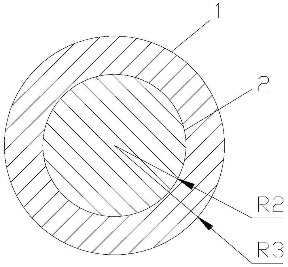
[0063] Model size figure 2 Image: Ambient temperature T c Set to 22 ° C, the conductor 2 of the cable takes Cu, the radius of 2 mm, the insulating layer 1 takes PA66, the maximum radius of 3 mm, the air convection heat dissipation coefficient α is 25w / m 2 · K, conductor 2 and insulation 1 material properties are as follows:

[0064] density Thermal Conductivity Compare Kg / M 3

W / m · k J / KG · K Cu 8900 377 390 PA66 1350 0.3 1100

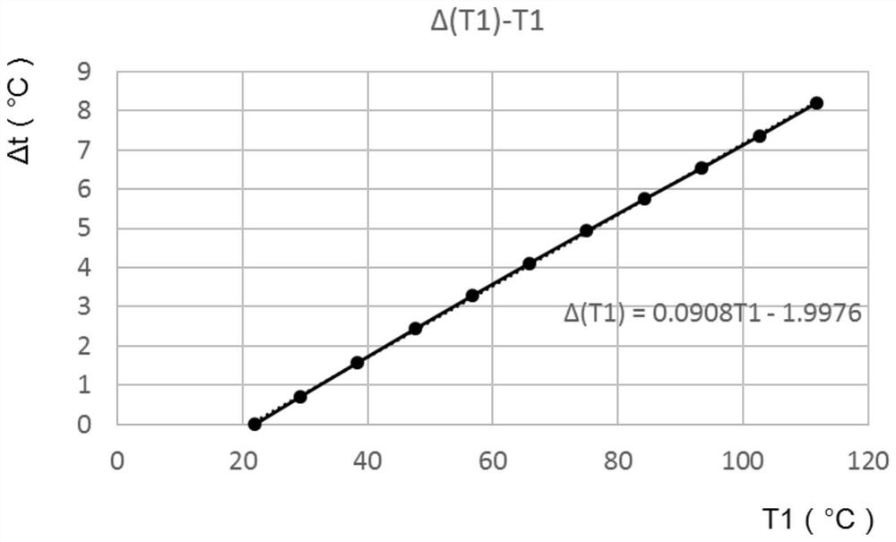
[0065] Established a mathematical model of cable in ANSYS, simulating δ t -T 1 Curve image 3 As shown, it can be obtained by simulation results. t = 0.0908t 1 -1.9976, gumped (3)

[0066]

[0067] Reated R t = 5500W / m · k, λ t = 0.3W / m · k, r 1 = 0.003m, r 2 = 0.002m, r = 0.00137Ω, α = 25w / m 2 · K, T c = 22 ° C into the above formula

[0068]

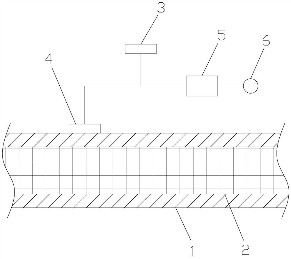
[0069] The external surface temperature T measured by the temperature probe one 4 measured by the temperature probe 1 The controller 5 calculates the condu...

Embodiment 2

[0071] It is basically the same as the embodiment, just ambient temperature T c Set to 32 ° C, build a mathematical model of cable in ANSYS, simulation get δ t -T 1 Curve Figure 4 As shown, it can be obtained by simulation results. t = 0.0906T 1 -2.8992, substitute (3)

[0072]

[0073] Reated R t = 5500W / m · k, λ t = 0.3W / m · k, r 1 = 0.003m, r 2 = 0.002m, r = 0.00137Ω, α = 25w / m 2 · K, T c = 32 ° C into the above formula

[0074]

[0075] The external surface temperature T measured by the temperature probe one 4 measured by the temperature probe 1 The controller 5 calculates the conductive 2 current I according to the formula (7), and the rated current I with the conductor 2 0 Comparison, if i> i 0 Then explain the flow of the flow exceeds the allowable value, the controller 5 controls the buzzer, issues an alarm, prompting the staff to pay attention.

Embodiment 3

[0077] Model size figure 2 Image: Ambient temperature T c Set to 22 ° C, the cable conductor 2 takes Al, the radius is 2 mm, the insulating layer 1 takes PA66, the maximum radius is 3 mm, the air convection heat dissipation coefficient α is 25w / m 2 · K, conductor 2 and insulating layer 1 The size and material properties are as follows:

[0078] density Thermal Conductivity Compare Kg / M 3

W / m · k J / KG · K Al 2700 237.5 880 PA66 1350 0.3 1100

[0079] Established a mathematical model of cable in ANSYS, simulating δ t -T 1 Curve Figure 5 , By simulation results can be δ t = 0.0923T1-2.0306, giving in the formula (3)

[0080]

[0081] Reated R t = 4500W / m · k, λ t = 0.3W / m · k, r 1 = 0.003m, r 2 = 0.002m, r = 0.00222Ω, α = 25w / m 2 · K, T c = 22 ° C into the above formula

[0082]

[0083] The external surface temperature T measured by the temperature probe one 4 measured by the temperature probe 1 The controller 5 calculates ...


PUM


Abstract

The invention discloses a cable load measuring device based on finite element simulation, and relates to the technical field of cable load measuring equipment, including a temperature probe one, a temperature probe two, a controller and an alarm, a temperature probe one and a temperature probe two and the alarm are electrically connected to the controller respectively. The cable includes a conductor and an insulating layer wrapped outside the conductor. The temperature probe 1 is fixed on the surface of the insulating layer, and the temperature probe 2 is exposed to the air. The finite element simulation is stored in the controller. program package, as well as relevant parameters for conductor material and insulating layer material. The invention also discloses a measuring method of the cable load measuring device based on finite element simulation. The invention only needs to measure the ambient temperature and the temperature of the outer surface of the cable insulation layer to monitor the cable load in real time, without connecting an ammeter and other equipment to the cable conductor, and without drilling holes in the cable insulation layer, and without interrupting the power supply, and is easy to operate , very safe, reliable, simple and efficient.

Description

Technical field [0001] The present invention relates to the technical field of cable load measuring equipment, in particular, a cable load measuring device and measurement method based on finite element simulation. Background technique [0002] The lights are clear, and the Words are in the beginning. These words are undoubtedly the light of the lights, which requires the light of the wire and cable, and the wire is used for power-on tools, but sometimes the user purchases the wires to be purchased. Small or some electrical voltage is larger than the load of the wire, it is easy to cause the wire overload. Wire and cable overload work will bring extremely serious consequences, so-called wire overload is called "overload". As is a car load capacity of 1 ton, but the weight of the cargo in the transport exceeds this regulation, then it has become "overload", which is not only easy to damage the vehicle. And it is possible to cause relevant traffic safety issues, the wires used in o...

Claims


Application Information

Patent Timeline
Patent Type & Authority Patents(China)
IPC IPC(8): G06F30/23
CPCG06F30/23
Inventor 刘小毛屈风景王社兵
Owner 深圳市安讯实业有限公司
Why Eureka
Try Eureka