Data transmission method and apparatus, and network system

A data transmission method and data technology, applied in the field of communication, can solve the problems of increased power consumption of UE and reduced standby time of UE, etc.

Active Publication Date: 2018-09-21
CHINA UNITED NETWORK COMM GRP CO LTD
View PDF11 Cites 8 Cited by
  • Summary
  • Abstract
  • Description
  • Claims
  • Application Information

AI Technical Summary

Problems solved by technology

[0005] Embodiments of the present invention provide a data transmission method, device, and network system, which solves the problem that in the prior art, in a communication system using dual connectivity technology, when UE transmits service data, it always needs to establish a connection with the primary base station and secondary base station. The communication connection increases the power consumption of the UE, which in turn reduces the standby time of the UE.

Method used


Image

  • Data transmission method and apparatus, and network system
  • Data transmission method and apparatus, and network system
  • Data transmission method and apparatus, and network system

Examples


Embodiment 1

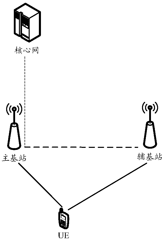
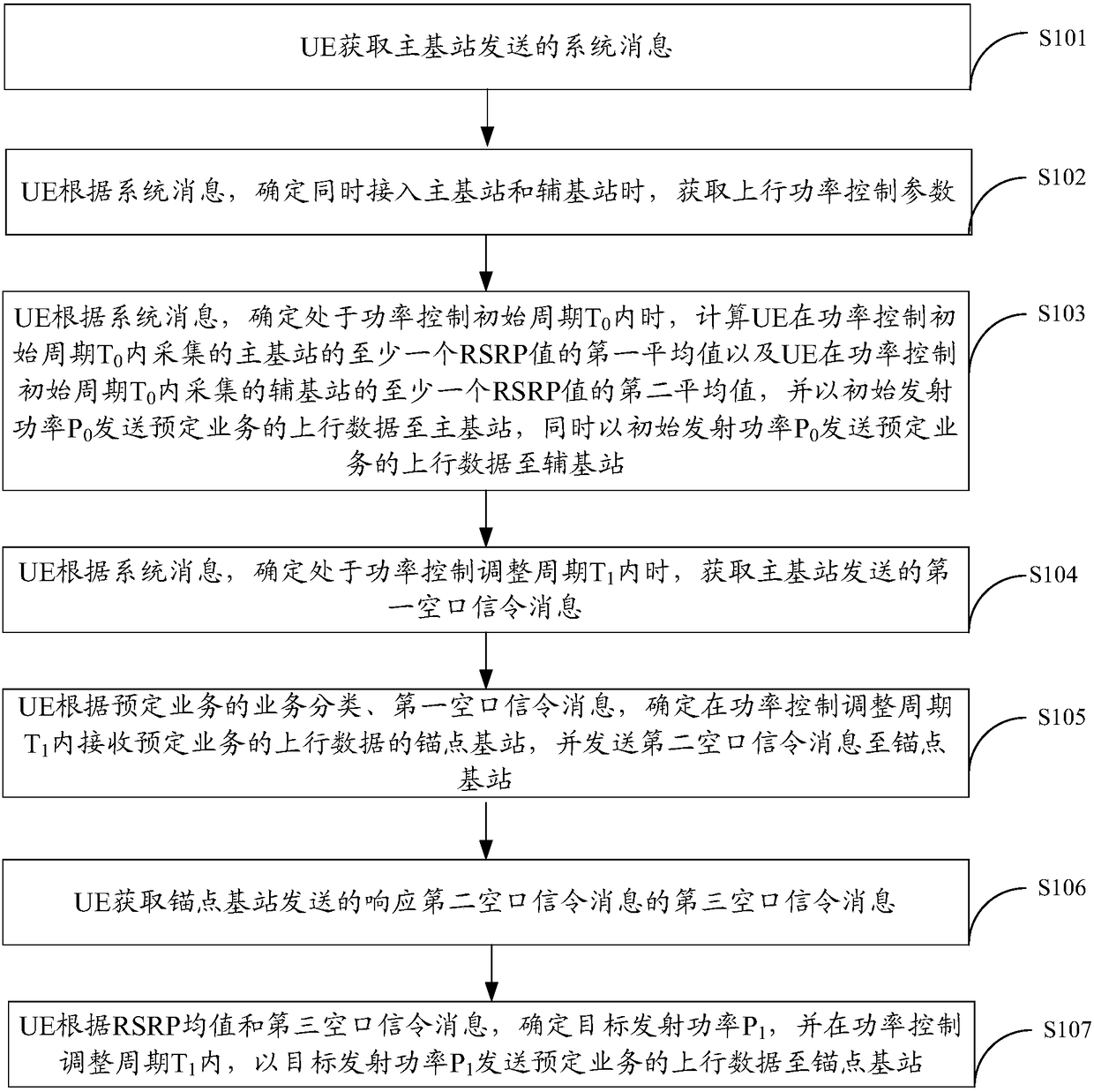
[0044] Embodiment 1. The embodiment of the present invention provides a data transmission method, such as figure 2 Shown include:

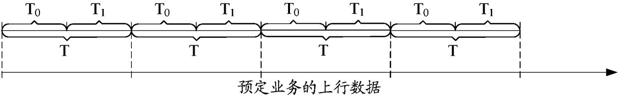
[0045] S101. The UE obtains the system message sent by the primary base station; wherein, the system message is used to instruct the UE to obtain uplink power control parameters when determining to simultaneously access the primary base station and the secondary base station; the uplink power control parameters include: power control period T, power control initial cycle T 0 and power control adjustment period T 1 , and T=T 0 +T 1 ; The system message is also used to instruct the UE to determine that it is in the power control initial period T 0 When within, calculate the UE in the power control initial period T 0 The first average value of at least one RSRP value of the primary base station collected within the period and the UE in the power control initial period T 0 The second average value of at least one RSRP value of the secondary bas...

Embodiment 2

[0092] Embodiment 2. The embodiment of the present invention provides a UE10, such as Figure 8 Shown include:

[0093] The obtaining module 101 is configured to obtain a system message sent by the primary base station 20; wherein, the system message is used to instruct the UE10 to obtain uplink power control parameters when determining to simultaneously access the primary base station 20 and the secondary base station 30; the uplink power control parameters include: power control Period T, power control initial period T 0 and power control adjustment period T 1 , and T=T 0 +T 1 ; The system message is also used to instruct the UE10 to determine that it is in the power control initial period T 0 When , calculate the UE10 in the power control initial period T 0 The first average value of at least one RSRP value of the primary base station 20 collected within the period and the initial period T of the power control of the UE10 0 The second average value of at least one RSR...

Embodiment 3

[0112] Embodiment 3. The embodiment of the present invention provides a main base station 20, such as Figure 9 Shown include:

[0113] The sending module 203 is configured to send a system message to the UE10; where the system message is used to instruct the UE10 to obtain uplink power control parameters when determining to simultaneously access the primary base station 20 and the secondary base station 30; the uplink power control parameters include: power control period T, Power control initial period T 0 and power control adjustment period T 1 , and T=T 0 +T 1 ; The system message is also used to instruct the UE10 to determine that it is in the power control initial period T 0 When , calculate the UE10 in the power control initial period T 0 The first average value of at least one RSRP value of the primary base station 20 collected within the period and the initial period T of the power control of the UE10 0 The second average value of at least one RSRP value of the ...


PUM


Abstract

The embodiment of the invention provides a data transmission method and apparatus, and a network system, and relates to the technical field of communication. The following problem in the prior art issolved: in a communication system adopting the dual-connection technology, when UE transmits service data, a communication connection always needs to be established between a primary base station anda secondary base station, which increases the power consumption of the UE, thus shortening the standby time of the UE. The method comprises the following steps: when it is determined that the UE is ina power control adjustment period T1 according to a system message, the UE obtains a first air interface signalling message sent by the primary base station; the UE determines an anchor base stationthat receives the uplink data of predetermined service within the power control adjustment period T1 according to a service category of the predetermined service and the first air interface signallingmessage, and sends a second air interface signalling message to the anchor base station; and the UE determines target transmitting power P1 according to an RSRP mean and a third air interface signalling message, and sends the uplink data of the predetermined service to the anchor base station at the target transmitting power P1. The data transmission method and apparatus provided by the embodiment of the invention are used for manufacturing UE and base stations.

Description

technical field [0001] The present invention relates to the technical field of communication, in particular to a data transmission method, device and network system. Background technique [0002] In the mobile communication system, in order to improve the system throughput, dual connectivity (English full name: DualConnectivity, abbreviated: DC) technology is introduced to support user equipment in the radio resource control (English full name: Radio ResourceControl, abbreviated: RRC) connection state. (English full name: User Equipment, abbreviated as: UE) simultaneously uses wireless resources provided by two base stations, and the two base stations can be connected through non-ideal transmission. [0003] Such as figure 1 As shown, in a communication system using dual connectivity technology, the UE maintains a connection with the main base station (full name in English: MastereNodeB, MeNB for short) and the secondary base station (full name in English: Secondary eNodeB,...

Claims


Application Information

Patent Timeline
Patent Type & Authority Applications(China)
IPC IPC(8): H04W52/02H04W52/14H04W52/24H04W76/15
CPCH04W52/0209H04W52/146H04W52/245H04W76/15Y02D30/70
Inventor 吕婷曹亘冯毅张涛李轶群
Owner CHINA UNITED NETWORK COMM GRP CO LTD
Why Eureka
Try Eureka