
Flow field optimization device capable of improving capacity of coal mill

An optimization device and coal mill technology, which is applied in the direction of grain processing, can solve the problems of reducing coal mill output, high energy consumption, and affecting the coal grinding effect, etc., to achieve improved output, simple structural design, and effective separation. Effect

Pending Publication Date: 2018-09-25
BEIJING SINO POWER RUNZE ENVIRONMENTAL PROTECTIONCO
View PDF0 Cites 2 Cited by
  • Summary
  • Abstract
  • Description
  • Claims
  • Application Information

AI Technical Summary

Problems solved by technology

[0002] When the coal mill is grinding coal powder, the raw coal falls from the coal drop pipe to the grinding disc of the coal mill, and is squeezed and ground into powder by the rotating grinding disc and the passive rolling grinding roller. During the grinding process, the coal powder and Raw coal and coal are moderately mixed together, and there is a phenomenon that the pulverized coal that has been ground is repeatedly ground, which greatly reduces the output of the coal mill, reduces the working efficiency of the coal mill, and also affects the coal. The grinding effect is high, and the energy consumption is also large

Method used


Image

  • Flow field optimization device capable of improving capacity of coal mill
  • Flow field optimization device capable of improving capacity of coal mill
  • Flow field optimization device capable of improving capacity of coal mill

Examples


Embodiment

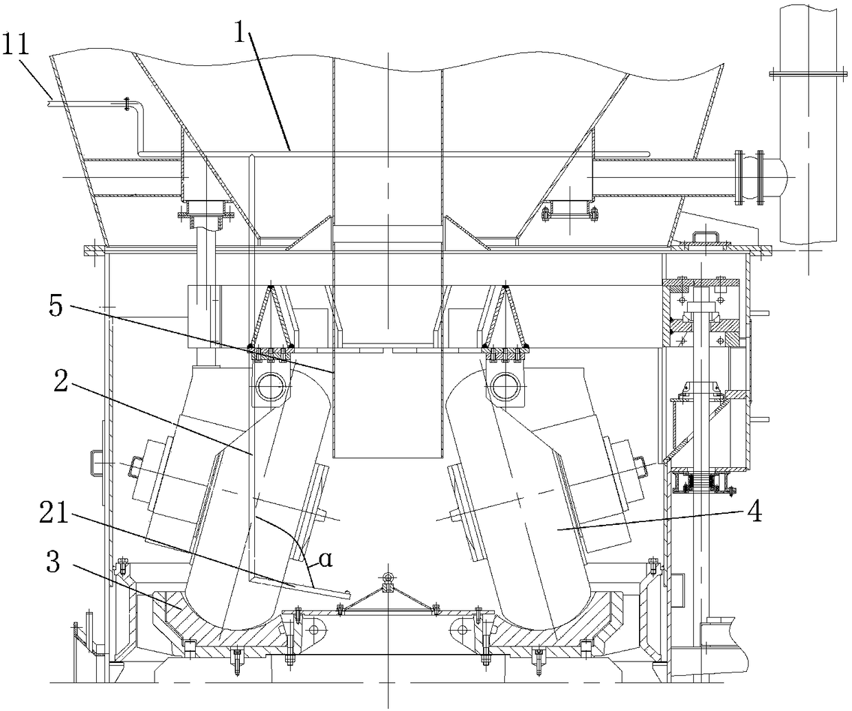
[0033] Example: such as Figures 1 to 4 As shown, the flow field optimization device for improving the output of the coal mill in this embodiment includes an air inlet pipe 1 and three air guide pipes 2;

[0034] The above-mentioned air inlet pipe 1 is arranged above the millstone 3 of the coal mill, and its air inlet extends out of the above-mentioned coal mill, and is externally connected to the air source;

[0035] Inside the coal mill, there are three grinding rollers 4 that are evenly spaced along the circumference of the above-mentioned grinding table 3 and are in rolling contact with the upper part of the grinding table 3, and the coal drop pipe 5 of the coal mill is located above the middle part of the above-mentioned grinding table 3;

[0036] The three above-mentioned air guide pipes 2 are respectively arranged vertically above the edge of the above-mentioned grinding disc 3 along the circumferential direction uniformly and at intervals, and are respectively located ...


PUM


Abstract

The invention relates to a flow field optimization device capable of improving the capacity of a coal mill. The flow field optimization device comprises an air inlet pipe and three air guide pipes, wherein an air inlet of the air inlet pipe stretches out of the coal mill and is externally connected with an air source; the coal mill is internally provided with three milling rollers which are uniformly distributed along the peripheral direction of a milling disc at intervals; a coal falling pipe of the coal mill is located above the middle part of the milling disc; the three air guide pipes areuniformly and vertically arranged above an edge of the milling disc at intervals along the peripheral direction respectively, and are located at the outer sides of the two adjacent milling rollers respectively; the upper ends of the air guide pipes are connected and communicated with the air inlet pipe respectively; a blowing air pipe, which obliquely extends toward the center of the milling disc,is arranged at the lower end of each air guide pipe; a plurality of air outlet holes, which are used for blowing air toward the milling disc, are formed in the lower parts of the blowing air pipes along the length direction; a spraying nozzle, which is used for blowing the air upward, is connected and communicated with the upper end of one end, far away from the corresponding air guide pipe, of each blowing air pipe. The flow field optimization device provided by the invention has the advantages that the structure design is simple and reasonable; ground coal powder and raw coal can be effectively separated in time, and the capacity of the coal mill is improved.

Description

technical field [0001] The invention relates to coal pulverizer equipment, in particular to a flow field optimization device for improving coal pulverizer output. Background technique [0002] When the coal mill is grinding coal powder, the raw coal falls from the coal drop pipe to the grinding disc of the coal mill, and is squeezed and ground into powder by the rotating grinding disc and the passive rolling grinding roller. During the grinding process, the coal powder and Raw coal and coal are moderately mixed together, and there is a phenomenon that the pulverized coal that has been ground is repeatedly ground, which greatly reduces the output of the coal mill, reduces the working efficiency of the coal mill, and also affects the coal. The grinding effect is high, and the energy consumption is also large. Contents of the invention [0003] The technical problem to be solved by the present invention is to provide a flow field optimization device for improving the output ...

Claims


Application Information

Patent Timeline
IPC IPC(8): B02C15/00B02C21/00B02C23/26
CPCB02C15/00B02C21/00B02C23/26
Inventor 刘丹韩雪晴
Owner BEIJING SINO POWER RUNZE ENVIRONMENTAL PROTECTIONCO
Learn More