Supercharge Your Innovation With Domain-Expert AI Agents!

Material conveying device

An equipment and material conveying technology, applied in the field of material transportation equipment, can solve problems such as low work efficiency, safety accidents, and high labor intensity of workers, and achieve the effects of reducing labor intensity, ensuring production safety, and improving work efficiency

Inactive Publication Date: 2018-09-25
CHANGDE FEIWO NEW ENERGY PARTS MFG
View PDF9 Cites 2 Cited by
  • Summary
  • Abstract
  • Description
  • Claims
  • Application Information

AI Technical Summary

Problems solved by technology

In the existing design, because the screw sleeve itself is easy to roll, and the screw sleeve must maintain a specified orientation before it can be successfully installed on the drilling machine, when the screw sleeve is installed on the drilling machine, it generally needs to be manually operated by workers. Very large, low work efficiency, and easily lead to safety accidents

Method used


Image

  • Material conveying device
  • Material conveying device
  • Material conveying device

Examples


Embodiment Construction

[0016] In order to enable those skilled in the art to better understand the technical solutions in the present application, the technical solutions in the embodiments of the present application will be clearly and completely described below in conjunction with the drawings in the embodiments of the present application. Obviously, the described The embodiments are only some of the embodiments of the present application, but not all of them.

[0017] Based on the embodiments in this application, all other embodiments obtained by persons of ordinary skill in the art without creative efforts shall fall within the scope of protection of this application.

[0018] In the description of the present invention, it should be understood that the orientation or positional relationship indicated by the terms "above", "below", "front end", "rear end" and the like are based on the orientation or positional relationship shown in the accompanying drawings, and are only In order to facilitate t...


PUM


Abstract

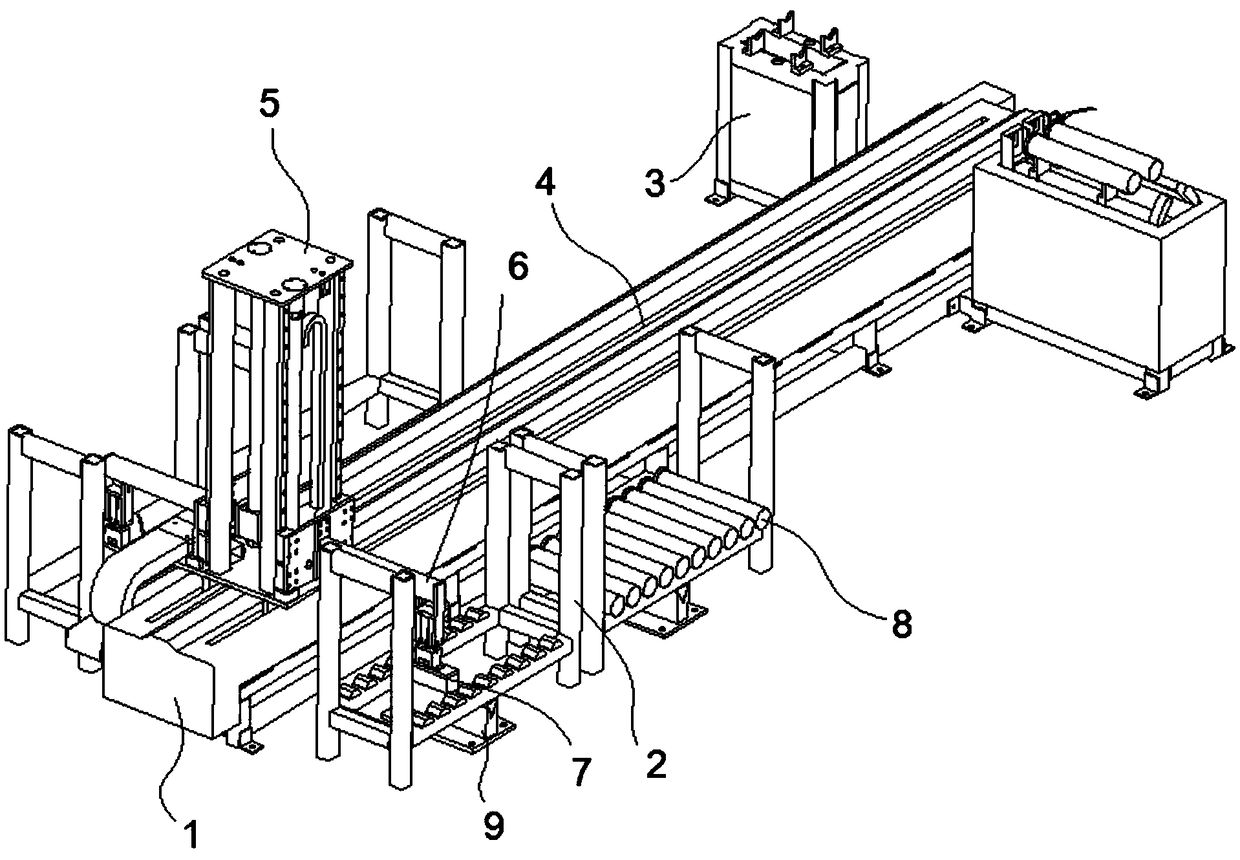
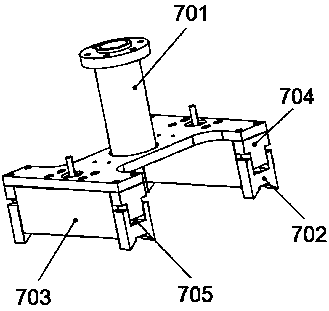
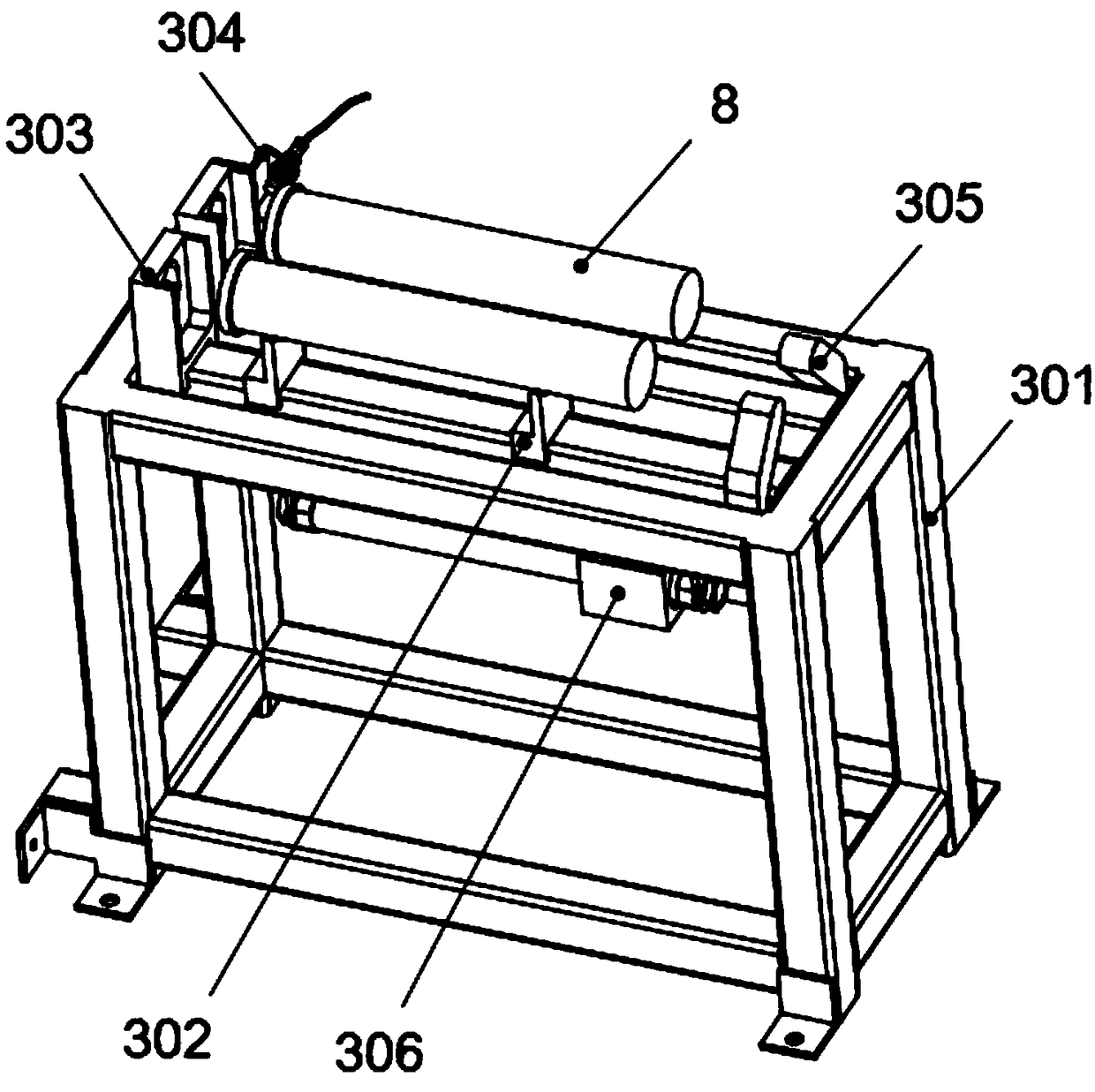
The invention discloses a material conveying device which comprises a rack. A material frame is arranged at the front end of the rack and is used for storing workpieces to be treated, a positioning table is arranged at the rear end of the rack and is used for adjusting and limiting the orientations of the workpieces to be treated, a guiding rail for communicating the material frame and the positioning table is arranged above the rack, a supporting frame is installed in the guiding rail in a sliding way, a supporting rod capable of lifting in the vertical direction is arranged on the supportingframe, and a gripper is arranged on the supporting rod and used for grabbing the workpieces to be treated. The workpieces to be treated are grabbed through the gripper, then the supporting rod drivesthe gripper to move up, the supporting frame drives the supporting rod to move from the material frame to the positioning table, the gripper places the workpieces to be treated on the positioning table for orientation adjustment and limiting, and finally next treatment of the workpieces to be treated can be achieved through a device externally connected with the positioning table. Therefore, automatic feeding of barrel type workpieces can be easily achieved, the labor intensity of workers is effectively reduced, the working efficiency is improved, and production safety is ensured.

Description

technical field [0001] The present invention relates to the field of material transportation equipment, more specifically, to a material conveying equipment. Background technique [0002] A wind turbine is a device that converts the kinetic energy of the wind into mechanical kinetic energy, and then converts the mechanical energy into electrical kinetic energy. The principle of wind power generation is to use the wind to drive the blades of the windmill to rotate, and then increase the speed of rotation through the speed increaser to drive the generator to generate electricity. According to the current windmill technology, power generation can be started at a breeze speed of about three meters per second (the degree of breeze); moreover, wind power generation does not require the use of fuel, nor does it generate radiation or air pollution. Therefore, it has been widely used more and more. Wind turbines generally include three parts: wind rotor, generator and iron tower. T...

Claims


Application Information

Patent Timeline
Patent Type & Authority Applications(China)
IPC IPC(8): B23Q7/04B23Q7/16
CPCB23Q7/04B23Q7/165
Inventor 陈志波陈玲赵全育
Owner CHANGDE FEIWO NEW ENERGY PARTS MFG
Features
  • R&D
  • Intellectual Property
  • Life Sciences
  • Materials
  • Tech Scout
  • Unparalleled Data Quality
  • Higher Quality Content
  • 60% Fewer Hallucinations
Learn More