Building-material stirring equipment

A technology for mixing equipment and building materials, which is applied to cement mixing devices, unloading devices, clay preparation devices, etc. It can solve the problems of mixing bucket mixing dead angle, difficult to clean, time-consuming and labor-intensive, etc., to improve mixing speed, save labor costs, The effect of reducing time cost

Inactive Publication Date: 2018-09-25
苏州相城埭辰科技产业发展有限公司
View PDF5 Cites 4 Cited by
  • Summary
  • Abstract
  • Description
  • Claims
  • Application Information

AI Technical Summary

Problems solved by technology

The existing problems are: (1) it is usually necessary to manually add water to the mixing tank while stirring, which is time-consuming and laborious; (2) the mixing blade is generally set at the middle and lower part of the stirring shaft, and the rotation range of the stirring blade is certain, so the memory of the mixing tank In the dead corner of stirring; (3) The slurry formed by stirring is easy to stick to the inner wall of the mixing barrel, which is difficult to clean

Method used


Image

  • Building-material stirring equipment

Examples


Embodiment Construction

[0021] The following is further described in detail through specific implementation methods:

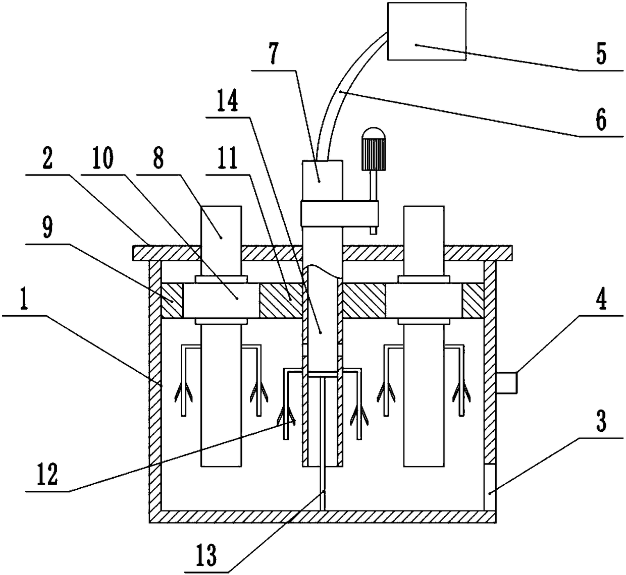
[0022] The reference signs in the drawings of the description include: mixing bucket 1, cover plate 2, discharge port 3, guide block 4, water bucket 5, water inlet pipe 6, stirring shaft 7, rotating shaft 8, inner ring gear 9, driven gear 10 , Drive gear 11, stirring blade 12, piston rod 13, water outlet trough 14.

[0023] Such as figure 1 As shown, the construction material mixing equipment includes a frame on which a mixing tank 1 is arranged, and the inner wall of the mixing tank 1 is provided with spike-like protrusions. A stirring shaft 7 is rotatably connected to the frame, and four rotating shafts 8 are rotatably connected to the surrounding of the stirring shaft 7 on the frame. The driving gear 10, the inner wall of the mixing tank 1 is spline connected with the inner ring gear 9 meshing with the driven gear 10, the frame is fixedly connected with a pole, the lower end of ...


PUM


Abstract

The invention belongs to the field of building processing and particularly discloses building-material stirring equipment. The building-material stirring equipment comprises a stirring barrel, whereina guide block is arranged on the outer wall of the stirring barrel, and a spiral groove is formed in a rack; the rack is also rotatably connected with a stirring shaft and rotary shafts; the lower ends of the stirring shaft and the rotary shafts extend into the stirring barrel respectively, and stirring blades are respectively arranged on the stirring shaft and the rotary shafts along the peripheral direction; a driving gear is arranged on the stirring shaft, the rotary shafts are provided with driven gears meshed with the driving gear, and inner gear rings meshed with the driven gears are arranged on the inner wall of the stirring barrel; a water discharging groove is formed in the bottom part of the stirring shaft and is internally provided with a piston in a sliding and connecting manner, a piston rod is fixedly connected to the lower side of the piston, and the lower end of the piston rod is fixed at the bottom part of a piston barrel; a water inlet is formed in the top part of the stirring shaft, a water outlet is formed in the side wall of the stirring shaft, a water feeding pipe is rotatably connected with the water inlet, a water barrel is also arranged on the rack, and one end, which is far from the stirring shaft, of the water feeding pipe is communicated with the water barrel. The building-material stirring equipment disclosed by the invention has the beneficial effect that by adoption of the scheme, the requirement of automatically filling water in the stirring process is met.

Description

technical field [0001] The invention belongs to the field of building processing, and in particular relates to a building material stirring device. Background technique [0002] In the construction industry, cement is one of the essential materials. The use of cement is usually as follows: continuously add water to the cement, stir while adding water, so that the water and cement are fully mixed, and finally stirred into a slurry. [0003] The mixing process usually requires the use of a mixer. The mixer includes a mixing bucket and a stirring shaft connected to the mixing bucket. Cement is thrown into the mixing bucket, and the stirring is achieved by rotating the mixing shaft. The existing problems are: (1) it is usually necessary to manually add water to the mixing tank while stirring, which is time-consuming and laborious; (2) the mixing blade is generally set at the middle and lower part of the stirring shaft, and the rotation range of the stirring blade is certain, so ...

Claims


Application Information

Patent Timeline
Patent Type & Authority Applications(China)
IPC IPC(8): B28C5/32B28C7/12B28C7/16
Inventor 廖成涛
Owner 苏州相城埭辰科技产业发展有限公司
Why Eureka
Try Eureka