[0022] The present invention will be further described in detail below in conjunction with specific embodiments.
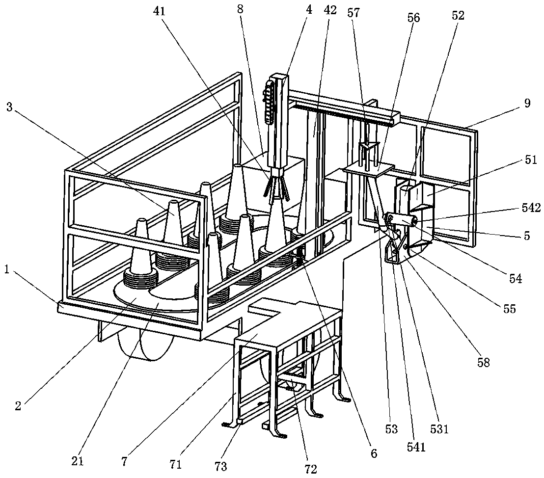
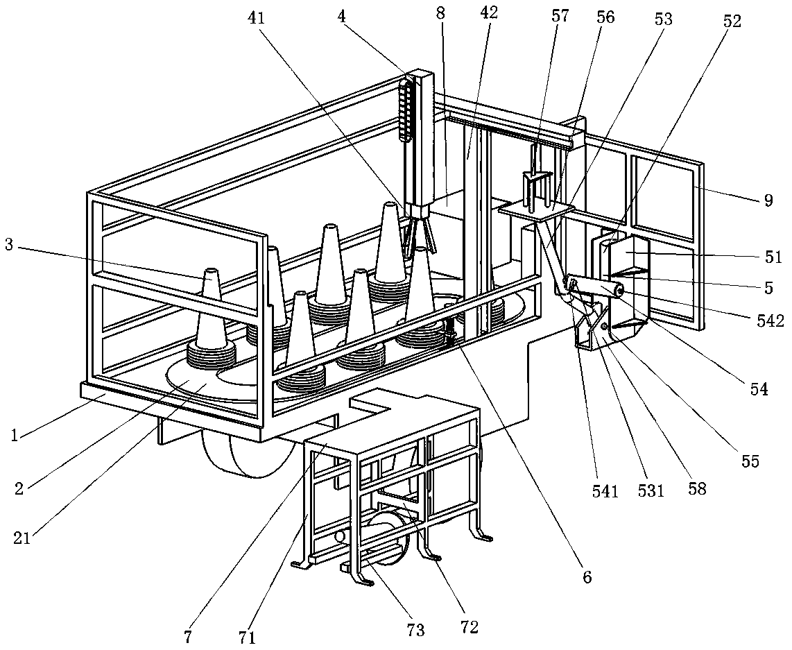
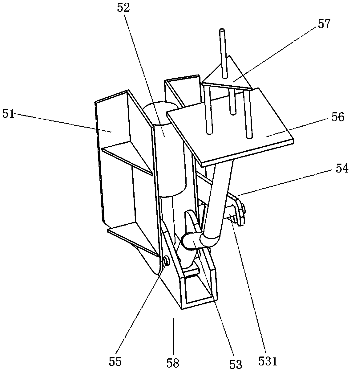
[0023] A reflective cone automatic retractable equipment, combined Figure 1 to Figure 5 As shown, it includes a car body 1, a reflective cone feeding mechanism 2, a feeding and receiving mechanism 5, a pushing and swinging mechanism 7, a generator 8, a clamping mechanism 4, a bottom clamping mechanism 6 and a controller.
[0024] The vehicle body 1 can drive the entire device to travel. The reflective cone feeding mechanism 2 is arranged on the vehicle body 1 and is used for intermittently feeding the reflective cone 3. The feeding and receiving mechanism 5 is arranged on the outer side of the vehicle body 1 and is used for intermittent feeding and receiving operations on the reflective cone. The pushing and swinging mechanism 7 is arranged on the outer side of the car body 1 and is flush with the feeding and receiving mechanism 5, and is used for centering and pushing down the reflective cone. The generator 8 is arranged on the vehicle body 1 to provide electrical energy for the entire device. The controller is arranged on the car body 1 and is used to control the reflective cone feeding mechanism 2 and the feeding and receiving mechanism 5 to coordinate operations.
[0025] The reflective cone feeding mechanism 2 includes a conveyor belt 21 and a driving motor. The conveyor belt 21 is arranged on the vehicle body and is used for placing and conveying the reflective cone. The controlled end of the drive motor is connected to the output end of the controller, and the drive motor is used to drive the conveyor belt 21 to move intermittently.
[0026] The feeding and rewinding mechanism 5 includes a swing rod 53, a positioning plate 51, a hydraulic cylinder 52, a pin shaft 55, an angle connector 58 and a clamping structure. The swing rod 53 can swing up and down to realize the reflective cone feeding and receiving operations; the positioning plate 51 is fixedly arranged on the car body 1 through the feeding and receiving mechanism fixing frame 9 and is provided with a pair; the hydraulic cylinder 52 is fixedly arranged between the two positioning plates 51 In between, the output shaft end of the hydraulic cylinder 52 is connected to the swing rod 53 through a cross plate, and the controlled end of the hydraulic cylinder 52 is connected to the output end of the controller for driving the swing rod 53 to rotate; the angle connecting piece 58 is connected through a pin 55 The hinge is arranged at the bottom end of the swing rod 53, and the two sides of the angle-shaped connector 58 are fixedly arranged on the inner side of the positioning plate 51; the clamping structure is arranged at the end of the swing rod 53 for placing the positioning reflective cone.
[0027] The clamping structure includes a reflective cone placement plate 56 and a reflective cone positioning column 57. The reflective cone placement plate 56 is arranged at the end of the swing rod 53 to hold the reflective cone; the reflective cone positioning post 57 is fixedly arranged above the reflective cone placement plate 56 and is used to be clamped inside the reflective cone to prevent the reflective cone from swinging left and right.
[0028] In order to enable the swing lever 53 to rotate better, a swing lever connecting shaft 531 is transversely provided in the middle of the swing lever 53, and the swing lever connecting shaft 531 is connected to the positioning plate 51 through the swing lever connecting plate 54. One end of the swing lever connecting plate 54 is provided with a swing lever connecting plate bayonet 541, the swing lever connecting plate bayonet 541 is clamped with the swing lever connecting shaft 531, and the other end of the swing lever connecting plate 54 is hinged through the swing lever connecting plate shaft 542 Set on the positioning plate 51.
[0029] The material pushing and swinging mechanism 7 includes a rail truss 71, a material pushing plate 72 and a reflective cone centralizing longitudinal rod 73. The track truss 71 is fixedly arranged on the side of the car body 1 and is used to guide the reflective cone; the middle of the track truss 71 is provided with a pusher plate 72 transversely, which is used to push down the reflective cone during the rewinding operation; A reflective cone centralizing longitudinal rod 73 is longitudinally arranged on the inner side of the bottom of the front end of the truss 71, and the reflective cone centralizing longitudinal rod 73 is used to automatically raise the reflective cone during the unloading operation.
[0030] A clamping mechanism 4 is arranged above the reflective cone feeding mechanism 2, and the clamping mechanism 4 is arranged on the vehicle body 1 through a bracket 42 for clamping a single reflective cone on the reflective cone feeding mechanism 2. The vehicle body 1 next to the reflective cone feeding mechanism 2 is provided with a bottom material clamping mechanism 6, and the bottom material clamping mechanism 6 is used to clamp the bottom of the reflective cone that does not need to be clamped.
[0031] The material clamping mechanism 4 includes a material feeding manipulator 41, which is arranged on a bracket 42. The controlled end of the material clamping mechanism 4 is connected to the output end of the controller for grasping a single reflective cone and capable of moving up and down.
[0032] The bottom clamping mechanism 6 includes a screw fixing plate 62, a screw 61, a nut 64, a connecting frame 66, an ultra-thin clamping plate 65, a micro cylinder 68 and a stepping motor 63, and the controlled end of the bottom clamping mechanism 6 is connected At the output of the controller. The screw fixing plate 62 is fixedly arranged on the car body 1; the screw 61 is arranged between the screw fixing plates 62 through a bearing; the screw nut 64 is matched with the screw 61, and the screw 61 can drive the screw 64 to move up and down when the screw 61 rotates. The connecting frame 66 is set on the side wall of the nut 64 through the spring 67; the ultra-thin clamping plate 65 is fixedly arranged at one end of the connecting frame 66, and is used to insert between the bottoms of the two reflective cones to realize the clamping of the bottom of the reflective cones Work; the micro-cylinder 68 is arranged at the other end of the connecting frame 66, used to drive the connecting frame 66 and the ultra-thin clamping plate 65 to move intermittently; the stepping motor 63 is connected to the input end of the lead screw 61 through a coupling, step The controlled end of the incoming motor 63 is connected to the output end of the controller for driving the lead screw 61 to rotate intermittently.
[0033] When the present invention needs to perform the reflective cone discharging operation, the reflective cone on the conveyor belt 21 is conveyed forward; the reflective cone feeding mechanism 2 is provided with a feeding cycle, and the bottom clamping mechanism 6 is in the stop of the reflective cone feeding mechanism 2 The stepping motor 63 is operated to drive the lead screw 61 to rotate. The screw nut 64 drives the ultra-thin clamping plate 65 to move to the gap between the reflective cone and the reflective cone to be clamped. At this time, the piston rod of the miniature cylinder 68 extends to push the connecting frame 66 and the ultra-thin clamping plate 65 move forward to the gap between the reflective cone to be clamped and the reflective cone to block the reflective cone under the reflective cone to be clamped, so that the feeding manipulator 41 can only clamp one reflective cone at a time; The manipulator 41 clamps the reflective cone and can drive the reflective cone to move up and down, left and right; the feeding manipulator 41 clamps the reflective cone onto the reflective cone placement plate 56 of the feeding and rewinding mechanism 5. The reflective cone positioning column 57 can position the reflective cone. Prevent the reflective cone from swinging from side to side; the feeding and receiving mechanism 5 discharges the reflective cone. The hydraulic shaft of the hydraulic cylinder 52 contracts and drives the swing rod 53 to rotate around the pin shaft 55. The swing rod 53 and the reflective cone set on the swing rod 53 are placed The plate 56 and the reflective cone positioning column 57 transport the reflective cone to the ground and put it down; the car body 1 continues to move forward, and the track truss 71 in the pusher and swing mechanism 7 plays a role in limiting and guiding the reflective cone. The straightening longitudinal rod 73 straightens the bottom of the downside-down reflective cone to complete the feeding operation of the reflective cone.
[0034] When the present invention needs to carry out the reflective cone receiving operation, the car body is reversed, and the reflective cone is pushed down by the pushing plate 72. At this time, as the car body retreats, the reflective cone positioning column 57 is inserted into the interior of the reflective cone. Hook the reflective cone; at this time, the hydraulic rod of the hydraulic cylinder 52 is extended, and the swing rod 53 and the reflective cone placement plate 56 and the reflective cone set on the swing rod 53 are lifted upward; the feeding manipulator 41 clamps and combines the reflective cone It is transported to the conveyor belt 21 to complete the collection operation.
[0035] The present invention can complete the automatic retracting and unfolding operation of the reflective cone in only 3 minutes, which greatly improves the work efficiency, reduces the manual operation time in the expressway lane, and reduces the hidden safety hazard.