
Fluid-chip separation device for metal cutting machines

A metal cutting and separation device technology, applied in metal processing machinery parts, filtration separation, separation methods, etc., can solve the problems of insufficient separation effect, inability to recover cutting fluid and debris, etc.

Inactive Publication Date: 2018-09-28
CHANGZHOU INST OF MECHATRONIC TECH
View PDF5 Cites 9 Cited by
  • Summary
  • Abstract
  • Description
  • Claims
  • Application Information

AI Technical Summary

Problems solved by technology

[0002] In the prior art, during the grinding process of the cutting machine tool, a large amount of fine iron filings will be generated. The chips in the prior art will affect the processing of the product, but the separation effect of the iron filing separation device in the prior art is not sufficient, and at the same time , after separation, it is impossible to recycle the cutting fluid and debris, so a new equipment is needed to solve the above problems

Method used


Image

  • Fluid-chip separation device for metal cutting machines
  • Fluid-chip separation device for metal cutting machines

Examples


Embodiment

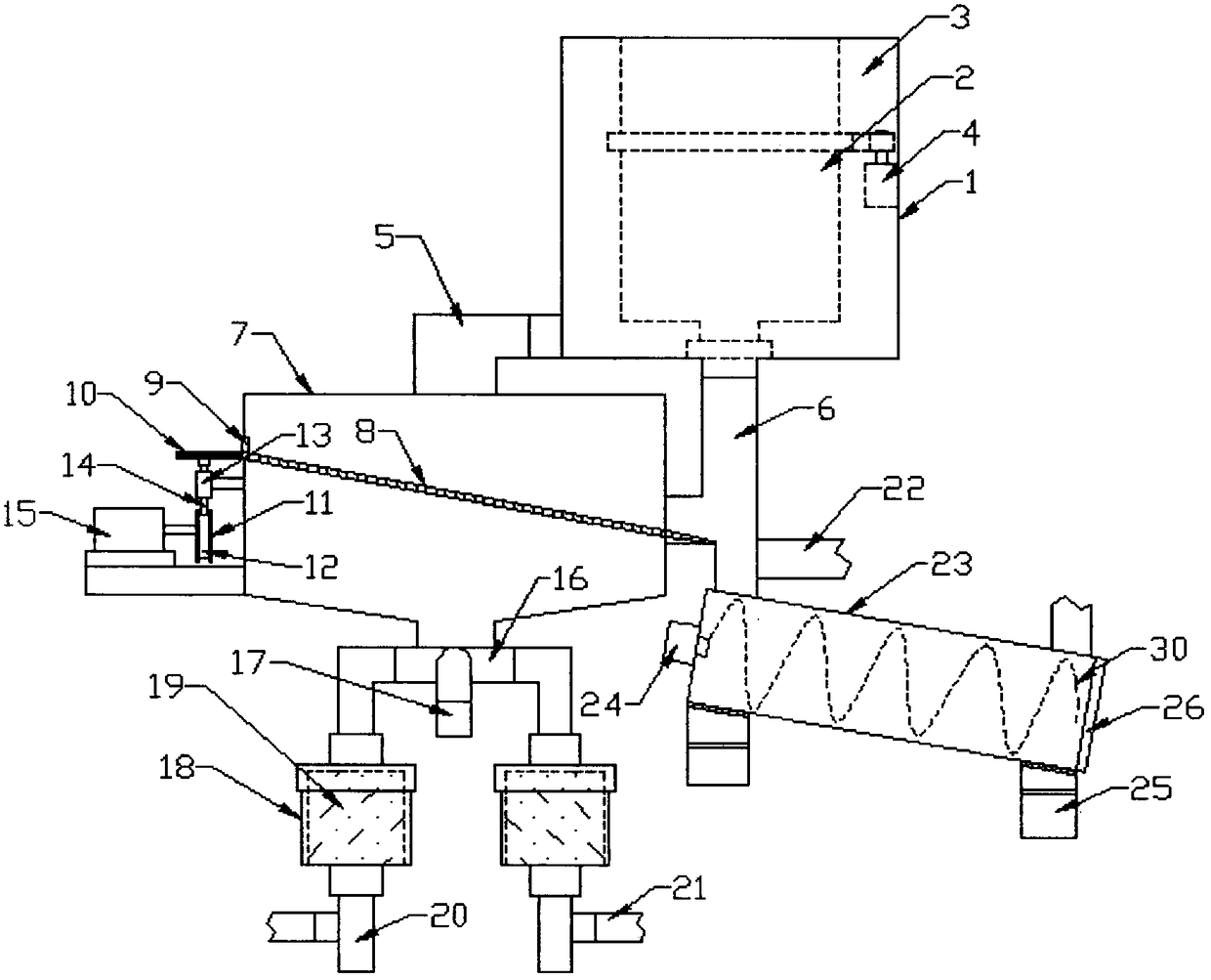
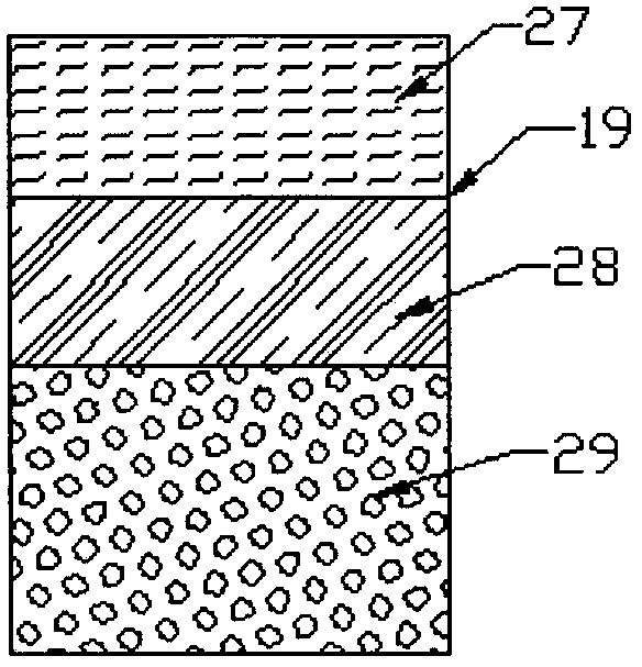
[0019] Example: such as Figure 1-2 As shown, the present invention is a liquid chip separation device for metal cutting machine tools, including a separator 1, the separator 1 includes a separation barrel 2, the separation barrel 2 is made of a filter screen 27, and the outer side of the separation barrel 2 is provided with a storage A No. 1 motor 4 is installed on the inner wall of the liquid chamber 3 and the liquid storage chamber 3. A No. 1 gear is fixed outside the output shaft of the No. 1 motor 4. A rack is fixed outside the separation barrel 2. The No. 1 gear is connected to the rack by a chain, and the storage One side of the bottom of the liquid chamber 3 is provided with a liquid outlet, and the liquid outlet is connected with a catheter 5, and the outlet of the catheter 5 is connected to the inlet of the separation box 7, and the outlet of the bottom of the separation barrel 2 Connect the chip guide tube 6, and the chip guide tube 6 is also connected to the separa...


PUM


Abstract

The invention discloses a fluid-chip separation device for metal cutting machines. Through the arrangement of a separator, a first motor is capable of driving a separation barrel to rotate. By means of centrifugation, a cutting fluid on metal chips is thrown to a fluid storage chamber, and thereby primary separation of large particulate metal chips and cutting fluid is implemented. A separation box is arranged such that secondary filtering of the cutting fluid is achieved. Filters are arranged, and therefore, final filtering of the filtered cutting fluid is achieved, and the cutting fluid is filtered completely. The total of two filters are arranged, and therefore, filter cores can be exchanged without stopping a machine. A washing machine is arranged, a conveying screw is disposed insidethe washing machine, and the chips can be stirred via the conveying screw. The flushing of the chips is achieved through distributing water to the washing machine via a second flushing pipe, and the chips are convenient to collect and reuse after flushing cleaning. In addition, a water delivery pipe which is capable of flushing the conveying screw reversely is arranged, and therefore, mesh holes inside the conveying screw are prevented from being blocked.

Description

technical field [0001] The invention relates to a liquid chip separation device, in particular to a liquid chip separation device for metal cutting machine tools. Background technique [0002] In the prior art, during the grinding process of the cutting machine tool, a large amount of fine iron filings will be generated. The chips in the prior art will affect the processing of the product, but the separation effect of the iron filing separation device in the prior art is not sufficient, and at the same time , After separation, it is impossible to recycle the cutting fluid and debris, so a new equipment is needed to solve the above problems. Contents of the invention [0003] The invention provides a liquid chip separating device for a metal cutting machine tool, which solves the problems in the background technology. [0004] In order to solve the problems of the technologies described above, the present invention provides the following technical solutions: [0005] The ...

Claims


Application Information

Patent Timeline
Patent Type & Authority Applications(China)
IPC IPC(8): B01D36/00B01D36/02B23Q11/00
CPCB01D36/00B01D36/02B23Q11/00
Inventor 刘锦武张江华
Owner CHANGZHOU INST OF MECHATRONIC TECH
Learn More