Motor shell surface paint spraying device
A technology of motor casing and spraying device, applied in the direction of spraying device, etc., can solve the problems of poor painting effect, lack of spraying effect of motor casing, poor clamping effect of motor casing, etc., and achieve good adjustability, efficient and fast paint spraying, The effect of simple and convenient clamping operation
- Summary
- Abstract
- Description
- Claims
- Application Information
AI Technical Summary
Problems solved by technology
Method used
Image

Examples
Embodiment 1
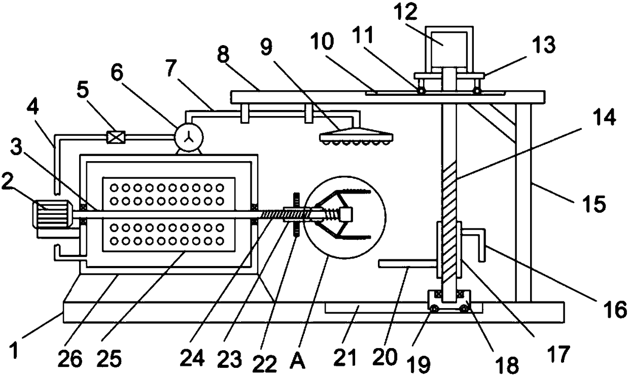
[0022] see Figure 1-3 , a motor housing surface paint spraying device, comprising a base plate 1, a support column 15 is vertically and fixedly installed on the base plate 1, a horizontal plate 8 is fixedly installed on the upper end of the support column 15, and a mixing bucket 26 is installed on the base plate 1 , the left side wall of the mixing bucket 26 is fixedly installed with a driving motor 2, the output shaft of the driving motor 2 is coaxially fixedly installed with a driving shaft 3 extending rightward through the mixing bucket 26, and the surface of the driving shaft 3 is fixedly equipped with a stirring mesh plate 25, through Start the drive motor 2 to realize the rotation and stirring of the paint in the mixing bucket 26, so as to promote the uniform mixing of the paint.
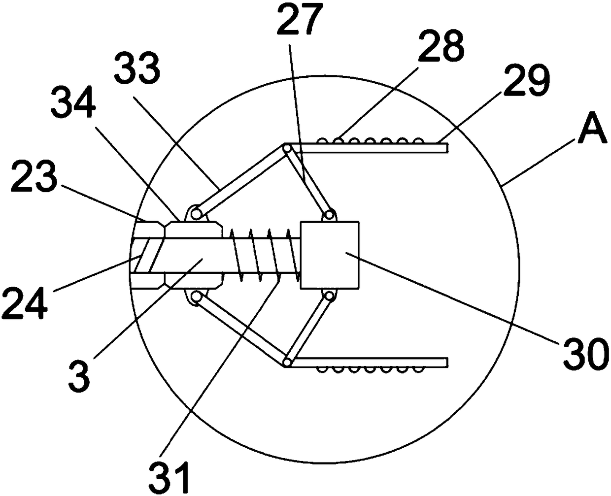
[0023] The drive shaft 3 is provided with an external thread 24, and the surface of the drive shaft 3 is fixedly equipped with a stirring screen 25; the mixing bucket 26 is provided with a pa...
Embodiment 2
[0027] On the basis of Embodiment 1, since the right side of the support and clamping device is provided with a lifting device, the lifting device includes a support frame 13 and a forward and reverse motor 12 mounted upside down on the support frame 13, and the output shaft of the forward and reverse motor 12 is A ball screw 14 is fixedly installed coaxially, and the surface of the ball screw 14 is threaded and connected to a screw sleeve 17. The left side wall of the screw sleeve 17 is horizontally fixed with a bearing plate 20, and the right side wall of the screw sleeve 17 A handle 16 is fixedly installed; a second guide groove 21 is horizontally opened on the bottom plate 1, and a limit slider 18 is slidably embedded in the second guide groove 21, and the lower end of the ball screw 14 passes through the bearing and the limit slider 18 articulated. Before painting the motor casing, place the motor casing on the bearing plate 20, start the forward and reverse motor 12 to d...
Embodiment 3
[0029] On the basis of Embodiment 2, it also includes a paint spraying device including a lifting pump 6 fixed on the top of the mixing bucket 26, and the inlet end of the lifting pump 6 is communicated with and installed with a feed pipe 4 extending to the inner bottom of the mixing bucket 26, and the lifting pump The outlet end of 6 is connected with a discharge pipe 7, and the paint spraying disc 9 is installed on the end of the discharge pipe 7 away from the lift pump 6; a check valve 5 is installed on the feed pipe 4, and the conduction direction of the check valve 5 is along the The feed pipe 4 runs from the mixing drum 26 to the lift pump 6 . The lift pump 6 lifts the fully stirred paint in the mixing bucket 26 through the feed pipe 4, and pumps it into the paint spraying tray 9 through the discharge pipe 7 to realize the painting action on the motor casing, so that the surface of the rotating motor casing can Apply the paint evenly.
PUM
 Abstract
Description
Claims
Application Information
 - R&D
- Intellectual Property
- Life Sciences
- Materials
- Tech Scout
- Unparalleled Data Quality
- Higher Quality Content
- 60% Fewer Hallucinations
Browse by: Latest US Patents, China's latest patents, Technical Efficacy Thesaurus, Application Domain, Technology Topic, Popular Technical Reports.
© 2025 PatSnap. All rights reserved.Legal|Privacy policy|Modern Slavery Act Transparency Statement|Sitemap|About US| Contact US: help@patsnap.com