Extrusion die-casting machine and extrusion die-casting process thereof

A technology of die casting machine and extrusion rod, applied in the fields of die casting and squeeze casting, can solve the problems of inability to eliminate pores, shrinkage holes, shrinkage porosity casting defects, difficult to accurately control the reserved gap, and insignificant extrusion effect, etc. Achieve the effect of reducing mold cost, low manufacturing cost and good versatility

Pending Publication Date: 2018-09-28
广东鸿特精密技术肇庆有限公司
View PDF2 Cites 10 Cited by
  • Summary
  • Abstract
  • Description
  • Claims
  • Application Information

AI Technical Summary

Problems solved by technology

Its shortcoming is that the piston of the extrusion cylinder pushes the side slider, and then pushes the extrusion core. The extrusion force is not directly extruded on the casting, and the direction of the force is changed by 90 degrees before it acts on the thickness direction of the casting; in addition Its structure is more complex, and each set of mold must be separately installed on the fixed platen with oblique pins, wedge blocks, movable mold cores, side sliders, extrusion cores, brackets, and extrusion cylinders, so the cost of the mold is high and the versatility is poor.
However, the molding part can only be pressurized as a whole through the mold. When the projected area of ​​the part is large, the extrusion force required is very large. If the tonnage of the equipment used is not enough, the extrusion effect will not be significant, or the pores cannot be eliminated. Shrinkage cavity, shrinkage porosity and other casting defects; if a large-tonnage equipment is used, additional energy will be consumed, which will increase manufacturing costs; and it is difficult to accurately control the reserved clearance when closing the mold

Method used


Image

  • Extrusion die-casting machine and extrusion die-casting process thereof

Examples


Embodiment 1

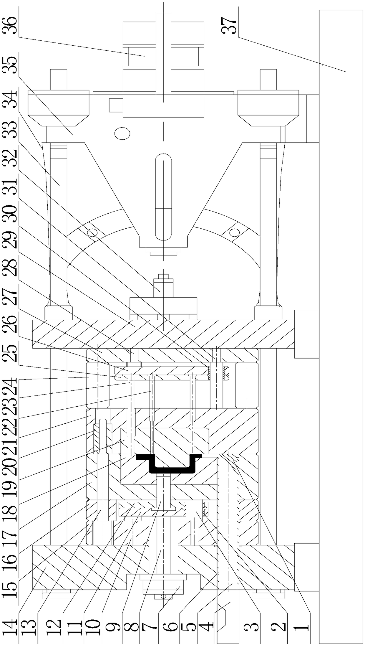
[0027] figure 1 It is a structural schematic diagram of an extrusion die-casting machine according to Embodiment 1 of the present invention, the front view, and the section between the fixed mold seat plate and the movable mold seat plate. Such as figure 1 As shown, the fixed mold seat plate 14 (also called the static mold seat plate or head plate), the movable mold seat plate 29 (also called the movable mold seat plate or the middle plate), and the tail plate 35 of the extrusion die casting machine in this embodiment are Installed on the body base 37 of the extrusion die-casting machine successively from left to right, the fixed mold base plate 14 is fixed on the upper left side of the body base 37, the tail plate 35 is fixed on the upper right side of the body base 37, and the movable mold base plate 29 is fixed on the upper right side of the body base 37. Between the mold base plate 14 and the tail plate 35, four connecting guide columns 33 connect the fixed mold base plat...

Embodiment 2

[0040] The design and process flow of a squeeze die-casting machine are basically the same as in Embodiment 1. The difference from Embodiment 1 is that this embodiment is provided with a plurality of The extrusion rods 9 correspond to the positions where the casting needs to be extruded and fed. The casting in this embodiment is a wheel-shaped part with 6 symmetrically distributed ribs, and there are 6 thick and large positions that are prone to shrinkage and shrinkage defects. The hot joint positions need to be squeezed and fed at the 6 thick and large positions . The specific method is: 6 extruding rods 9 are installed on the extruding push plate 11, corresponding to 6 thick and large positions of the casting. When closing the mold, the hydraulic system of the die-casting machine drives the piston 8 of the extrusion cylinder 7 to move to the left, and drives the six extrusion rods 9 fixed on the extrusion push plate 11 to move linearly to the left to reach the leftmost posi...


PUM


Abstract

The invention discloses an extrusion die-casting machine and an extrusion technology and die-casting technology combined extrusion die-casting process of the extrusion die-casting machine. The extrusion die-casting machine further comprises a small-stroke extrusion oil cylinder arranged on the outer side of a fixed die seat plate, a piston of the small-stroke extrusion oil cylinder moves to push an extrusion rod and directly extrudes a metal forming material stored in a storage space at the front part of the extrusion rod, so that the metal forming material enters a mold cavity, and performs local extrusion forming on the thickness direction of a semi-solid casting formed in the mold cavity. The extrusion die-casting machine has the advantage of being high in production efficiency, and meanwhile, has the function of reducing or eliminating shrinkage porosities and shrinkage cavities in thick part of a casting through an extruding method, so that the performance of the casting is obviously improved, and the machine is particularly suitable for manufacturing large-scale die castings. According to the extrusion die-casting machine and the extrusion die-casting process thereof, the structure is simple, the production cost is relatively low, and the effects of being stable and reliable are achieved; and the process method is convenient to operate, high in universality, easy to popularize and apply in the industry and wide in market application prospect.

Description

technical field [0001] The invention belongs to the technical fields of squeeze casting and pressure casting, and more specifically relates to a squeeze die-casting machine and a squeeze die-casting process which can obviously improve the performance of castings. Background technique [0002] With the continuous development of die-casting technology, higher requirements are put forward for the mechanical properties, complex procedures, and appearance of castings. In die-casting, especially for large-scale die-castings, there are more molten metals in the mold cavity. , it is relatively prone to shrinkage and porosity. Although there is a pressurization process in the die-casting process, for large castings, due to the heat accumulated in the molten metal in the thick and large parts of the cavity, the molten metal in this part solidifies Slower than other parts, the surrounding parts close to the cavity wall are solidified first, and a closed liquid pool is formed in the cen...

Claims


Application Information

Patent Timeline
Patent Type & Authority Applications(China)
IPC IPC(8): B22D17/08B22D18/02
CPCB22D17/08B22D17/007B22D18/02
Inventor 张金荣陆文兴
Owner 广东鸿特精密技术肇庆有限公司
Why Eureka
Try Eureka