
Automobile camshaft press-mounting machine

A press-fitting machine and camshaft technology, which is applied in workpiece clamping devices, metal processing, metal processing equipment, etc., can solve the problems of single feeding, low rotation accuracy, and high labor intensity, etc., and achieve a rotary clamping mechanism The effect of stability, reasonable overall structure design and high degree of automation

Pending Publication Date: 2018-09-28
HANGZHOU GAOPIN AUTOMATION EQUIP
View PDF1 Cites 2 Cited by
  • Summary
  • Abstract
  • Description
  • Claims
  • Application Information

AI Technical Summary

Problems solved by technology

[0002] The existing press-fit structure has the following defects: 1) Manual press-fit is time-consuming, labor-intensive, large errors, and low production efficiency; 2) The press-fit structure uses a servo motor, the screw is too thick, and the force point is not located Force center; 3) The rotation and clamping mechanism is unreliable, and the rotation accuracy is not high; 4) Without force monitoring, it is easy to cause safety hazards, and it is guaranteed by servo alone; 5) Only single feeding, and only press-fitting One product; 6) No centering mechanism; 7) The overall press-fit structure has low efficiency, high failure and poor accuracy
Although this patent can automatically load the camshaft when the camshaft and the signal wheel are pressed, so as to improve the press-fitting accuracy and production efficiency of the camshaft assembly tool; but the rotation and clamping mechanism is unreliable, the rotation accuracy is not high, and only a single material can be loaded , so it still has the above defects

Method used


Image

  • Automobile camshaft press-mounting machine
  • Automobile camshaft press-mounting machine
  • Automobile camshaft press-mounting machine

Examples


Embodiment Construction

[0037] The present invention will be further described in detail below in conjunction with the accompanying drawings and examples. The following examples are explanations of the present invention and the present invention is not limited to the following examples.

[0038] Example.

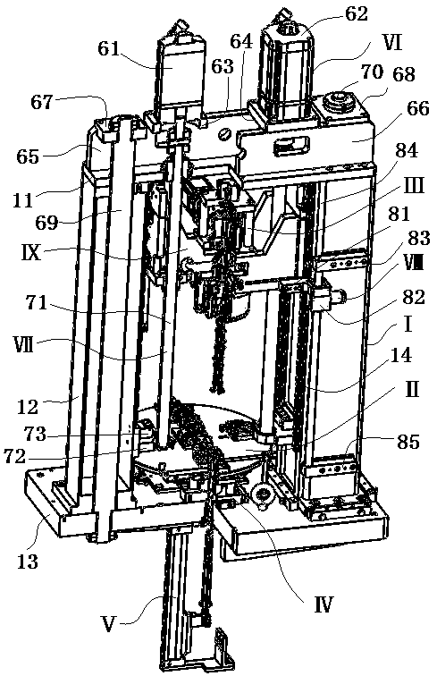
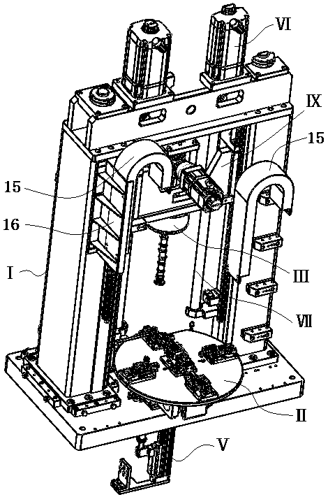
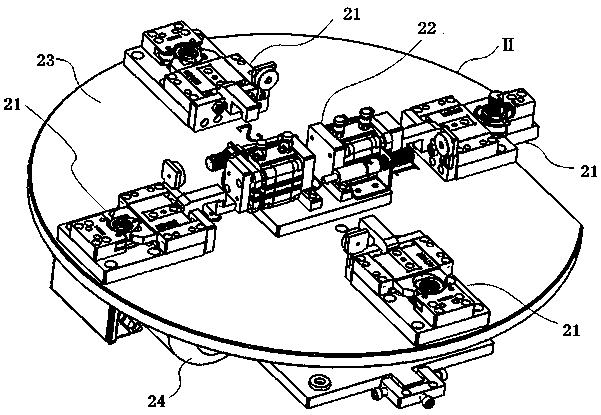
[0039] see Figure 1 to Figure 11 The automotive camshaft press assembly device in this embodiment mainly includes frame I, feeding turntable mechanism II, rotary clamping mechanism III, power mechanism VI, intermediate slider assembly IX, centering mechanism V, transmission mechanism VII, power mechanism VI Fixed on the frame I, the rotating clamping mechanism III is fixed on the middle slider assembly IX, the middle slider assembly IX is movably connected with the long rail structure 14 on the frame, the rotating clamping mechanism III is connected with the transmission mechanism VII, and the centering mechanism Ⅴ is fixed on the bottom plate 13 of the press, and the transmission mechanism VII i...


PUM


Abstract

The invention relates to an automobile camshaft press-mounting machine, and belongs to the field of automobile component press-mounting. The automobile camshaft press-mounting machine comprises a frame, a power mechanism, a rotating and clamping mechanism, a feeding turntable mechanism, an intermediate slider component, a centering mechanism and transmission mechanisms; the power mechanism is fixed to the frame, and the frame comprises a press fixing plate, a press column and a press baseplate; the press fixing plate is connected to the press baseplate through the press column, and the frame is provided with a long rail structure; the rotating and clamping mechanism is fixed to the intermediate slider component movably connected to the long rail structure on the frame, and the rotating andclamping mechanism is connected to the transmission mechanisms; and the center mechanism is fixed to the press baseplate, and the transmission mechanism is connected to the power mechanism. The automobile camshaft press-mounting machine is rational in design, safe and reliable, and the rotating and clamping mechanism is stable; and the automobile camshaft press-mounting machine has the advantagesof high working efficiency and precision, easy operation, and high degree of automation, and the usage requirements are met.

Description

technical field [0001] The invention relates to a device, in particular to a press-fitting device for an automobile camshaft, which belongs to the field of press-fitting of automobile parts. Background technique [0002] The existing press-fit structure has the following defects: 1) Manual press-fit is time-consuming, labor-intensive, large errors, and low production efficiency; 2) The press-fit structure uses a servo motor, the screw is too thick, and the force point is not located Force center; 3) The rotation and clamping mechanism is unreliable, and the rotation accuracy is not high; 4) Without force monitoring, it is easy to cause safety hazards, and it is guaranteed by servo alone; 5) Only single feeding, and only press-fitting One product; 6) No centering mechanism; 7) The overall press-fit structure has low efficiency, high failure and poor precision. [0003] The publication date is June 26, 2018, and the Chinese patent publication number 106217032B discloses an in...

Claims


Application Information

Patent Timeline
IPC IPC(8): B23P19/02B23P19/10B25B11/02B23P19/00
CPCB23P19/00B23P19/001B23P19/002B23P19/006B23P19/02B23P19/10B25B11/02
Inventor 张志刚赵志龙徐顺士万新灵
Owner HANGZHOU GAOPIN AUTOMATION EQUIP
Learn More