Die-cutting equipment and driving cam for lifting moving platform of die-cutting equipment

A technology for driving cams and moving platforms, which is applied in metal processing and other directions, and can solve the problems of large wear of transmission mechanisms, affecting the speed and effect of deep embossing and bronzing products, so as to ensure stable operation of equipment, improve speed and effect, and improve Effects on production efficiency and production quality

Active Publication Date: 2018-09-28
唐山嘉谊印刷机械有限公司
View PDF9 Cites 0 Cited by
  • Summary
  • Abstract
  • Description
  • Claims
  • Application Information

AI Technical Summary

Problems solved by technology

1. The crankshaft linkage mechanism has no dwell time when the moving platform is at a high position, which affects the speed and effect of deep embossing and bronzin

Method used


Image

  • Die-cutting equipment and driving cam for lifting moving platform of die-cutting equipment
  • Die-cutting equipment and driving cam for lifting moving platform of die-cutting equipment
  • Die-cutting equipment and driving cam for lifting moving platform of die-cutting equipment

Examples


Embodiment Construction

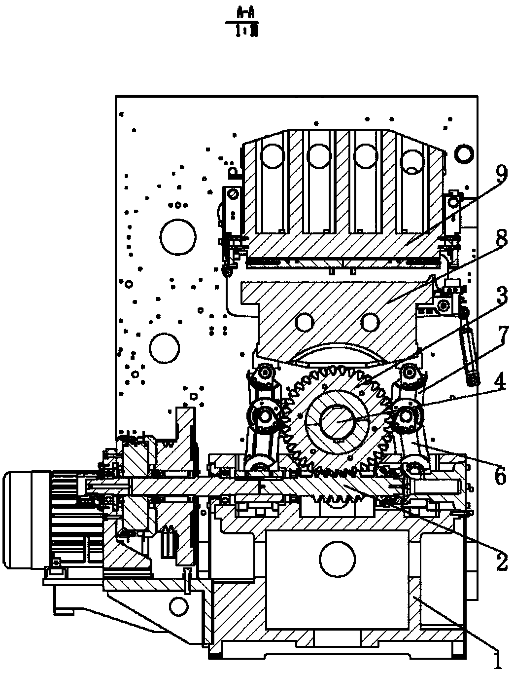
[0099] Such as Figure 5 to Figure 8 As shown, this embodiment provides a driving cam 10 for lifting the movable platform 8 of the die-cutting equipment, including a cam body 10-1, and the outline of the cam body 10-1 has an ascending curve 10-1-1 and A descending curve 10-1-2, a far-end resting curve 10-1-3 is connected between the distal end of the ascending curve 10-1-1 and the distal end of the descending curve 10-1-2.

[0100] Various improvements of this embodiment are described in detail below.

[0101] Such as Figure 5 As shown, the central angle corresponding to the distal rest curve 10-1-3 is 20 degrees. Of course, it may also be that the central angle corresponding to the distal rest curve 10-1-3 is 10 degrees. Alternatively, the central angle corresponding to the distal rest curve 10-1-3 is 30 degrees.

[0102] Such as Figure 5 and Figure 8 As shown, a near-end resting curve 10-1-4 is connected between the proximal end of the rising curve 10-1-1 and the pr...


PUM


Abstract

The invention discloses die-cutting equipment and a driving cam for lifting a moving platform of the die-cutting equipment. The driving cam comprises a cam main body, wherein the contour line of the cam main body comprises an ascending curve and a declining curve; and a far-end stopping curve is connected between the far end of the ascending curve and the far end of the declining curve. The die-cutting equipment comprises a base table and the movable platform which are connected by a lifting mechanism; the lifting mechanism comprises a lower oscillating arm and an upper oscillating arm; the upper end of the lower oscillating arm is articulated with the lower end of the upper oscillating arm; the lower end of the lower oscillating arm is articulated with the top surface of the base table; the upper end of the upper oscillating arm is articulated with the bottom surface of the moving platform; the lifting mechanism is in transmission connection with a cam mechanism; and the cam mechanismcomprises the driving cam as described above. When the moving platform is in a high position, the die-cutting equipment has remaining time, thus greatly increasing the speed and effect of deeply embossing and stamping products.

Description

technical field [0001] The invention relates to a driving component and packaging processing and forming equipment, in particular to a driving cam used for lifting the moving platform of the die-cutting equipment and the die-cutting equipment thereof. Background technique [0002] Die Cutting Machine (Die Cutting Machine), also known as beer machine, CNC, servo hydraulic stamping machine, is mainly used for die cutting of some non-metallic materials, stickers, EVA, double-sided tape, electronics, mobile phone protective film, etc. (full cut, half cut), indentation and bronzing operations, lamination, automatic waste discharge. The die-cutting machine uses a steel knife, a metal mold, a steel wire (or a template carved from a steel plate), and applies a certain pressure through the embossing plate to roll and cut the printed matter or cardboard into a certain shape. If the entire printed matter is cut into a single graphic product, it is called die-cutting; if the steel wire...

Claims


Application Information

Patent Timeline
IPC IPC(8): B26F1/38B26D5/16B26D7/26
CPCB26D5/16B26D7/2614B26F1/38
Inventor 关宗玉
Owner 唐山嘉谊印刷机械有限公司
Why Eureka
Try Eureka