A tire self-positioning system and method

A self-positioning, tire technology, applied in tire measurement, tire parts, vehicle parts, etc., can solve the problem that tire position information cannot be one-to-one correspondence, and achieve the effect of reducing data frame length, accurate and reliable positioning structure, and durable power

Active Publication Date: 2021-01-05
ZHEJIANG GEELY AUTOMOBILE RES INST CO LTD +1
View PDF23 Cites 0 Cited by
  • Summary
  • Abstract
  • Description
  • Claims
  • Application Information

AI Technical Summary

Problems solved by technology

[0006] In order to solve the problem that the tire position information displayed on the vehicle TPMS display unit cannot correspond to the actual tire position information after the user adjusts the four tire positions, the present invention provides a tire self-positioning method, and the specific technical solution is as follows:

Method used


Image

  • A tire self-positioning system and method
  • A tire self-positioning system and method
  • A tire self-positioning system and method

Examples


Embodiment 1

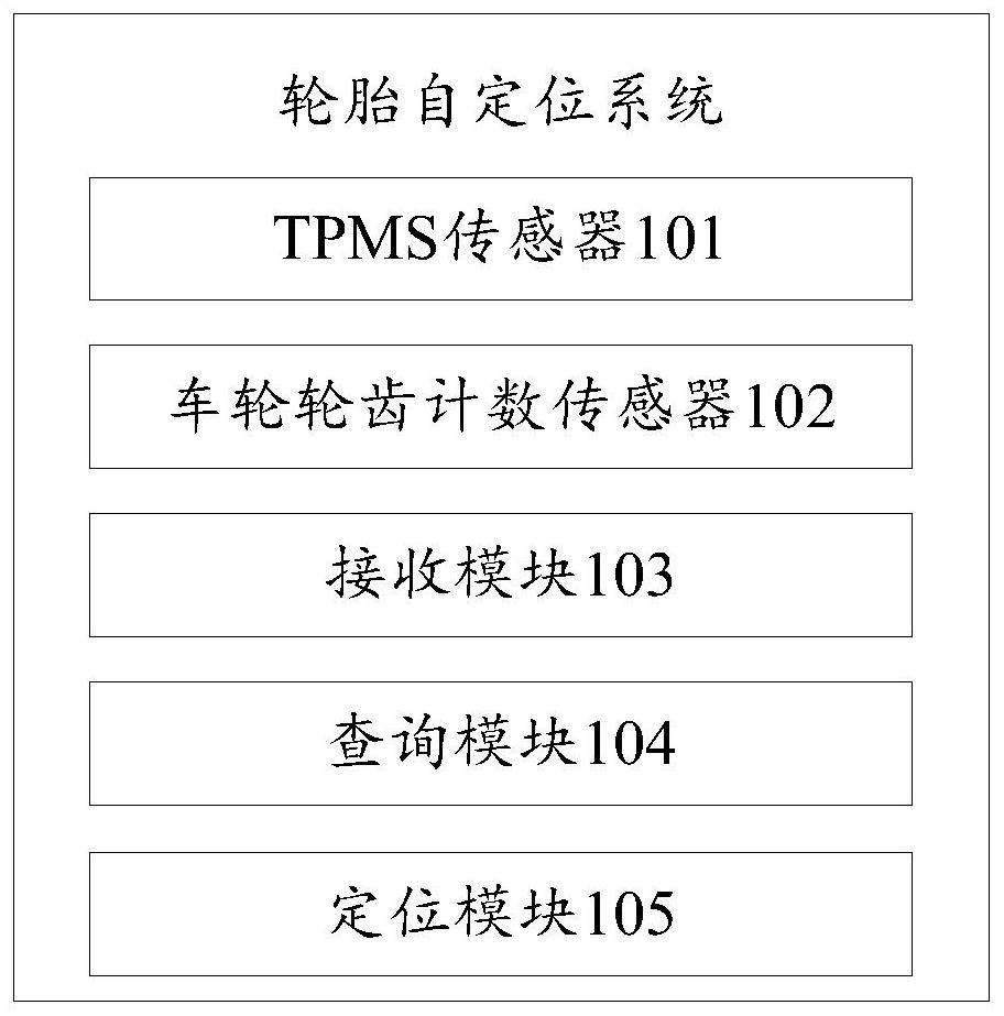
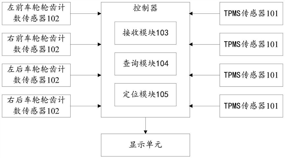
[0056] figure 1 It is a structural block diagram of a tire self-positioning system provided by an embodiment of the present invention, please refer to figure 1, a tire self-alignment system provided by the present embodiment includes the following modules:

[0057] The receiving module 103 is used to receive and store the positioning frame respectively according to the TPMS sensor ID, and receive and store respectively according to the wheel pair tooth number signal;

[0058] The TPMS sensor 101 is used to send a positioning frame to the receiving module 103 when the vehicle enters the motion mode from the parking mode; the positioning frame carries the TPMS sensor ID and the reversing time;

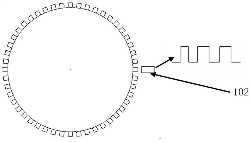
[0059] The wheel tooth count sensor 102 is used to collect the tooth number signal of the wheel and send it to the receiving module 103;

[0060] The query module 104 is used to query the tooth number signal according to the back time and the receiving time of the positioning frame, an...

Embodiment 2

[0085] Figure 9 It is a flow chart of a tire self-alignment method provided by the embodiment of the present invention, and for the sake of simplicity, only those steps related to the subject matter in the text are shown. The overall tire self-alignment method can have many other steps and can use many other types of equipment. Please refer to Figure 9 , the present embodiment provides a tire self-positioning method, comprising the following steps:

[0086] S201: The TPMS sensor sends a positioning frame to the receiving module when the vehicle enters the sports mode from the parking mode; the positioning frame carries the TPMS sensor ID and the reverse time;

[0087] S202: The wheel tooth count sensor collects the wheel tooth number signal and sends it to the receiving module;

[0088] S203: The receiving module receives and stores the positioning frame according to the TPMS sensor ID, and receives and stores the positioning frame according to the wheel pair tooth number...


PUM


Abstract

The invention provides a tire self-positioning system. The system comprises a receiving module used for receiving and storing positioning frames and tooth number signals, TPMS sensors used for sendingthe positioning frames to the receiving module when a vehicle enters in a motion mode from a parking mode and the TPMS sensors reach the specific positions, wheel tooth counting sensors used for acquiring the tooth number signals of all wheels and sending the tooth number signals to the receiving module, an inquiry module used for inquiring the tooth number signals according to the reversing moments and the receiving moments of the positioning frames, and a positioning module used for positioning IDs of the TPMS sensors to the wheels with the smallest variance and / or the smallest standard deviation, and therefore information displayed by a display unit corresponds to the actual positions of tires. The invention further provides a tire self-positioning method. The special positioning frames are adopted, the length of data frames is effectively reduced, a tire self-positioning algorithm is simplified, and the electric quantity of the TPMS sensors is more durable.

Description

technical field [0001] The invention relates to the technical field of automotive electronics, in particular to a tire self-positioning system and method. Background technique [0002] During the use of the vehicle, after the user adjusted the positions of the four tires, the tire information displayed on the TPMS display unit of the vehicle did not match the actual tire positions. The realization of the tire self-positioning function in the prior art has the following several ways: [0003] 1) The self-positioning method based on field strength is low in cost, and most of the functions can be realized through software algorithms, but it depends on the wiring of the car itself, which is susceptible to signal interference, and the algorithm is more complicated, making it difficult to realize; [0004] 2) The self-positioning method based on the external coding memory is less susceptible to signal interference and has a high success rate. However, additional external devices ...

Claims


Application Information

Patent Timeline
Patent Type & Authority Patents(China)
IPC IPC(8): B60C23/04
CPCB60C23/0416
Inventor 欧建平郑利利贾丹丽熊想涛
Owner ZHEJIANG GEELY AUTOMOBILE RES INST CO LTD
Why Eureka
Try Eureka