Al technical title is built by PatSnap Al team. It summarizes the technical point description of the patent document.
An iron wiper and wiper technology, applied in vehicle cleaning, vehicle maintenance, transportation and packaging, etc., can solve the problems of easy floating of the scraper arm, troublesome maintenance and replacement, small scraping area, etc., to achieve the connection The method is safe and reliable, convenient for maintenance and replacement, and the effect of increasing the scraping area
Pending Publication Date: 2018-09-28
瑞安市亚星汽车配件有限公司
View PDF4 Cites 4 Cited by
Summary
Abstract
Description
Claims
Application Information
AI Technical Summary
This helps you quickly interpret patents by identifying the three key elements:
Problems solved by technology
Method used
Benefits of technology
Problems solved by technology
[0003] The traditional high-speed rail wiper has single function, narrow use area, and no protection device. Excessive current may cause damage during operation; when the high-speed rail speed is fast, it is easy to cause slippage of the scraper arm joint; traditional high-speed rail wiper adjusts the pressure of the scraper arm , the pressure changes unevenly during mediation, and the scraper arm is easy to float when the vehicle is moving at high speed or meeting cars, resulting in the front windshield glass not being wiped clean; and the total length of the traditional high-speed rail wiper blade is short, the scraping area is small, and maintenance and replacement are troublesome , aiming at these defects, it is necessary to design a high-speed rail wiper system
Method used
Image
Click on the blue label to locate the original text in one second.
Reading with bidirectional positioning of images and text.
Examples
Embodiment Construction
[0025] The following will clearly and completely describe the technical solutions in the embodiments of the present invention with reference to the accompanying drawings in the embodiments of the present invention. Obviously, the described embodiments are only some, not all, embodiments of the present invention. Based on the embodiments of the present invention, all other embodiments obtained by persons of ordinary skill in the art without making creative efforts belong to the protection scope of the present invention.
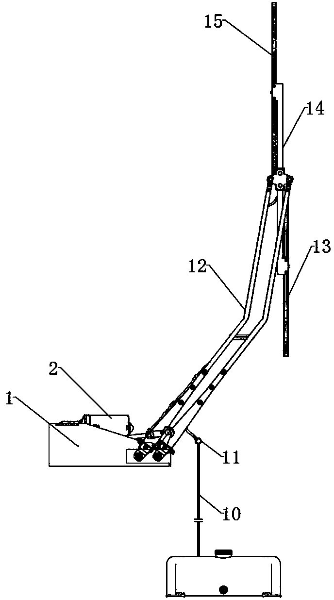
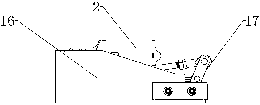
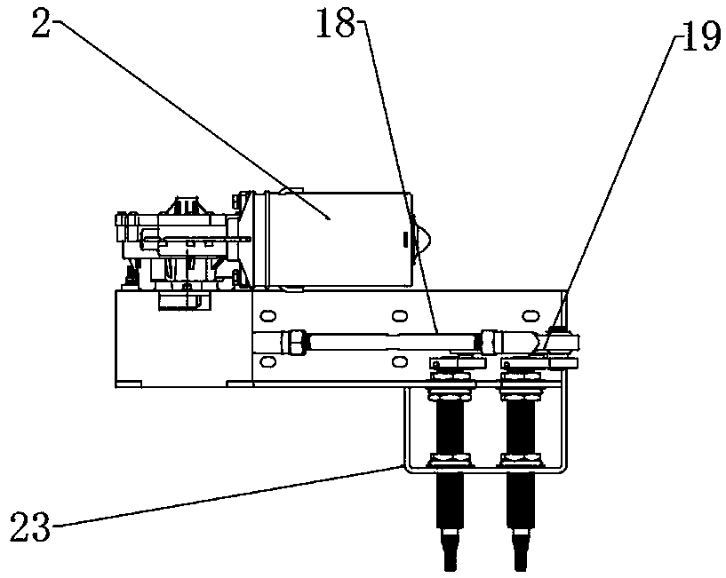
[0026] see Figure 1-8, the present invention provides a technical solution: a high-speed rail wiper system, including a drive assembly 1, a wiper motor interface 3, a control switch 4, a power interface 5, a wiper control box 6, a grounding hole 7, a washing Motor interface 8, water shortage sensor interface 9, water pipe 10, wall joint 11, scraper arm 12, first scraper 13, scraper connecting rod 14, second scraper 15, anti-floating block 25, copper scraper a...
PUM
Abstract
The invention discloses a high-speed railway wiper system. The high-speed railway wiper system comprises a driving assembly part, a wiper motor interface, a control switch, a wiper control box, a washing motor interface, a water-deficient sensor interface, a wall-penetrating joint, a scraping arm, a first scraping blade, a scraping blade connecting rod, a second scraping blade, an anti-floating block, a copper scraping arm joint, a scraping arm triangle, and a connecting arm, a scraping blade seat, an anti-loosening nut, a spring fixed rod, a fixed nut, a spring and a nozzle. The scraping blade connecting rod is fixed to one side of the scraping blade seat through a screw, the first scraping blade is fixed to one end of the scraping blade connecting rod through a screw, and the second scraping blade is fixed to the other end of the scraping blade connecting rod through a screw. According to the high-speed railway wiper system, two large load scraping blades are adopted in the first scraping blade and the second scraping blade, the two scraping blade are connected with the scraping blade connecting rod in a bolt mode, the total length of the scraping blades are increased, and the scraping area is increased, the connection mode is safe and reliable, the high-speed railway wiper system is durable and easy to repair and replace, and the high-speed railway wiper system can completely replace imported parts.
Description
technical field [0001] The invention relates to the technical field of wipers, in particular to a high-speed rail wiper system. Background technique [0002] With the growth of the domestic economy, the high-speed rail is also developing rapidly in our country, and has become China's national business card. At present, the Fuxing high-speed rail developed by China uses wipers imported from abroad. [0003] The traditional high-speed rail wiper has single function, narrow use area, and no protection device. Excessive current may cause damage during operation; when the high-speed rail speed is fast, it is easy to cause slippage of the scraper arm joint; traditional high-speed rail wiper adjusts the pressure of the scraper arm , the pressure changes unevenly during mediation, and the scraper arm is easy to float when the vehicle is moving at high speed or meeting cars, resulting in the front windshield glass not being wiped clean; and the total length of the traditional high-sp...
Claims
Application Information
Patent Timeline
Application Date:The date an application was filed.
Publication Date:The date a patent or application was officially published.
First Publication Date:The earliest publication date of a patent with the same application number.
Issue Date:Publication date of the patent grant document.
PCT Entry Date:The Entry date of PCT National Phase.
Estimated Expiry Date:The statutory expiry date of a patent right according to the Patent Law, and it is the longest term of protection that the patent right can achieve without the termination of the patent right due to other reasons(Term extension factor has been taken into account ).
Invalid Date:Actual expiry date is based on effective date or publication date of legal transaction data of invalid patent.