
A Space Deployment Mechanism Applied to Satellite Solar Wing

A space deployment and sun technology, applied in the aerospace field, can solve the problems of space deployment mechanism storage ratio, low power quality, and complicated drive of the solar wing mechanism

Active Publication Date: 2021-04-20
NANJING UNIV OF AERONAUTICS & ASTRONAUTICS
View PDF7 Cites 0 Cited by
  • Summary
  • Abstract
  • Description
  • Claims
  • Application Information

AI Technical Summary

Problems solved by technology

[0004] Although researchers have carried out in-depth and long-term research work in the field of space deployment mechanisms, there are still bottlenecks in the following two aspects: (1) the storage ratio and power quality of space deployment mechanisms are relatively low; (2) the traditional solar wing mechanism The driver is more complex

Method used


Image

  • A Space Deployment Mechanism Applied to Satellite Solar Wing
  • A Space Deployment Mechanism Applied to Satellite Solar Wing
  • A Space Deployment Mechanism Applied to Satellite Solar Wing

Examples


Embodiment Construction

[0065] The space deployment mechanism of the present invention will be described in detail below in conjunction with the accompanying drawings.

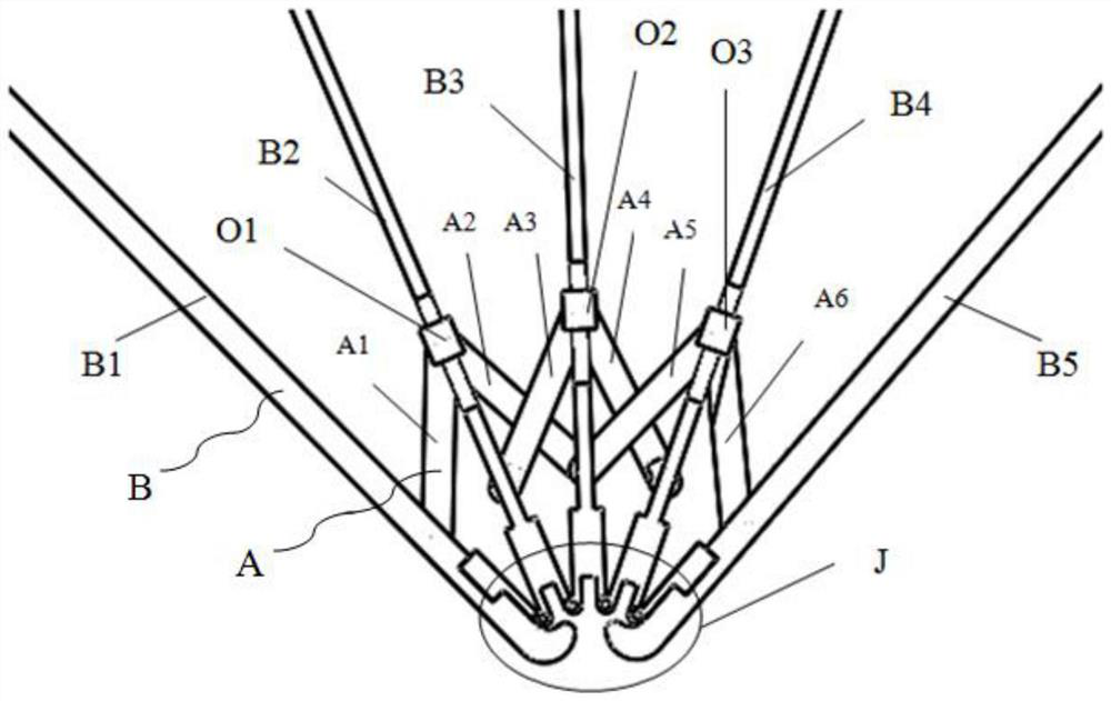
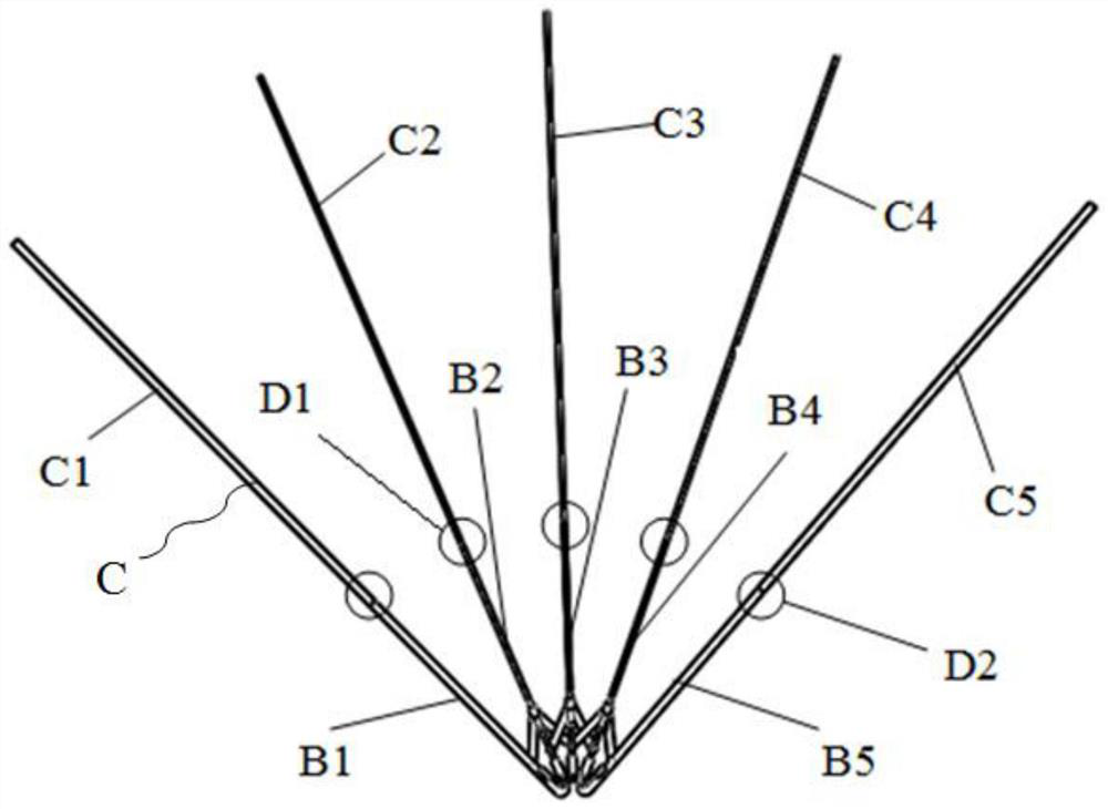
[0066] Such as figure 1 , figure 2 and Figure 12 The space deployment mechanism shown mainly includes: the second rod group B, the third rod group C, a synchronous deployment device and a driving mechanism;

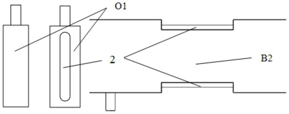
[0067] The second bar group B includes: bar 21 B1, bar 22 B2, bar 23 B3, bar 24 B4 and bar 25 B5 connected sequentially from top to bottom through the central hinge J, wherein bar 22 B2, A chute 2 is set on the bar two three B3 and the bar two four B4;

[0068] Center hinge J is specifically: the ends of bar two one B1, bar two two B2, bar two three B3, bar two four B4 and bar two five B5 are provided with pin holes and bearing pins, and the pin holes of bar two one B1 and The pin shaft of bar two two B2 is combined into a hinge, the pin hole of bar two two B2 is combined with the pin shaft of bar two three B3 to form a hi...


PUM


Abstract

The invention discloses a space deployment mechanism applied to satellite solar wings. The mechanism mainly includes a second rod group, a third rod group, a composite material film for light energy absorption, a synchronous deployment device and a drive mechanism, wherein the second The rod ends of the rod groups are connected sequentially through the central hinge, and the third rod group is connected with the second rod group through a self-locking hinge; the synchronous deployment device enables the second rod group to be deployed synchronously, and at the same time limits the deployment angle; the outermost part of the third rod group The rod is equipped with a motor as a drive. One end of the wire rope is fixed on the rod outside the third rod group, and the other end is connected to the motor on the other side of the mechanism. The second rod group and the third rod group are equipped with pulleys and pulleys respectively. The ring groove, the wire rope goes around the pulley and the ring groove, the motor rotates, and the pulling force is transmitted through the wire rope to realize the deployment of the whole mechanism. The structure of the invention is simple, compact and reliable, can realize the deployment of the solar wing of the spacecraft satellite, and has the advantages of high power-to-mass ratio, good stability and the like.

Description

technical field [0001] The invention belongs to the field of aerospace technology, and relates to a space deployment mechanism, in particular to a space deployment mechanism applied to satellite solar wings. Background technique [0002] With the advancement of aerospace technology and the increasing demands of human beings for space exploration, large-scale space deployment mechanisms have been used more and more, including large-aperture antennas and large-scale solar wings. Due to the limited envelope space of the rocket carrier cabin, the size of the space deployment mechanism will be strictly limited. [0003] There are many types of unfolding mechanisms, among which the rod-shaped frame type unfolding mechanism is more widely used and develops rapidly. Since it was first used on the U.S. Air Force S-3 satellite as a magnetometer bracket in 1975, it has been used on various spacecraft for many times. In recent years, with the success in the research of light-absorbing...

Claims


Application Information

Patent Timeline
Patent Type & Authority Patents(China)
IPC IPC(8): B64G1/44
CPCB64G1/222B64G1/443
Inventor 郭策简世康黄秋野俞志伟马耀鹏李新
Owner NANJING UNIV OF AERONAUTICS & ASTRONAUTICS
Learn More