
Yarn detector assembly

A wire detector and component technology, which is applied in the direction of conveying filamentous materials, thin material processing, transportation and packaging, etc., can solve problems such as breakage, poor integration, and high yarn tension, so as to increase detection accuracy and reduce production cost, the effect of simplifying the assembly process

Pending Publication Date: 2018-09-28
ZHEJIANG DONGXING TEXTILE MACHINERY
View PDF0 Cites 0 Cited by
  • Summary
  • Abstract
  • Description
  • Claims
  • Application Information

AI Technical Summary

Problems solved by technology

[0004] The photoelectric self-stop device currently used has good self-stop effect when the yarn breaks, but there are defects such as independent installation of auxiliary parts, poor integration, inconvenient installation and adjustment, and inconvenient maintenance after parts are damaged.
At the same time, because each component is installed separately, the yarn path is longer and the yarn tension is high, which may easily cause fluffing and breakage of the yarn, affecting production and yarn quality

Method used


Image

  • Yarn detector assembly
  • Yarn detector assembly
  • Yarn detector assembly

Examples


Embodiment

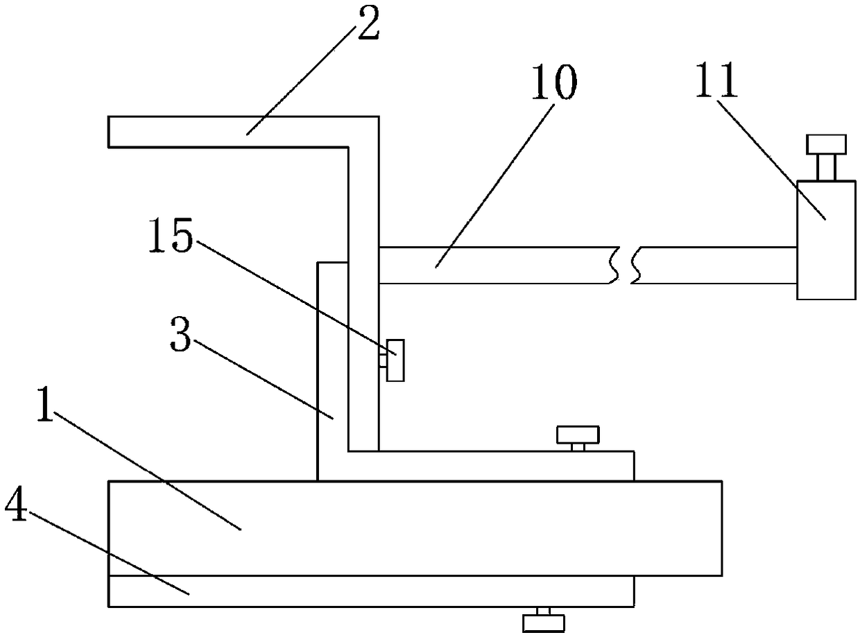
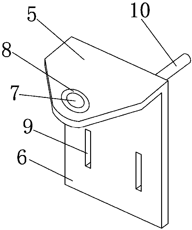
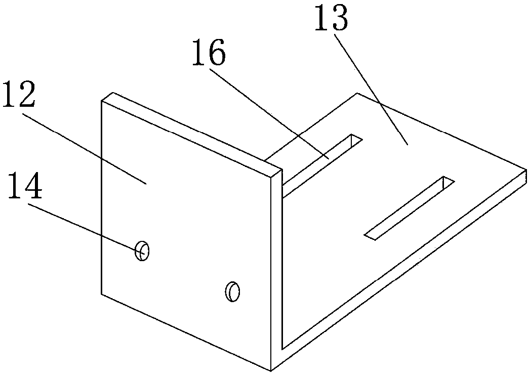
[0024] Embodiment: a kind of thread finder assembly, as Figure 1-Figure 9 As shown, it includes a thread finder, a first iron piece, a second iron piece and a third iron piece. The first iron piece is in an inverted “L” shape and includes a fan-shaped segment and a first vertical segment. The fan-shaped The end of the segment is provided with a first wire-passing hole, and an annular rubber ring is provided on the first wire-passing hole, and a first strip-shaped hole is provided on both sides of the first vertical section, and the first strip-shaped hole Above the first vertical section, a support rod is fixedly welded on the first vertical section, and the other end of the support rod is provided with a clamping device; the second iron sheet is "L"-shaped, including the second vertical section and the transverse Section, both sides of the second vertical section are provided with first bolt holes, when the second vertical section and the first vertical section are in contac...


PUM


Abstract

The invention belongs to the technical field of textile equipment, and discloses a yarn detector assembly. The yarn detector assembly comprises a yarn detector, a first iron sheet, a second iron sheetand a third iron sheet. The first iron sheet comprises a sector segment and a first vertical segment. A first yarn passing hole is formed in the end of the sector segment and provided with an annularrubber ring. First strip-shaped holes are formed in the two sides of the first vertical segment. The second iron sheet comprises a second vertical segment and a transverse segment. A second yarn passing hole is formed in the end of the third iron sheet and provided with an annular rubber ring. Third strip-shaped holes are formed in the two sides of the third iron sheet. According to the yarn detector assembly, the annular rubber rings are arranged on the first yarn passing hole and the second yarn passing hole, when yarn shakes too violently to impact on the annular rubber rings, the annularrubber rings can achieve a certain buffer function, the yarn can restore to the original position faster, and therefore the stability of infrared pulses received by the yarn detector is kept, and detection precision is increased.

Description

technical field [0001] The invention belongs to the technical field of textile equipment, and in particular relates to a thread detector assembly. Background technique [0002] The doubling machine is used as the pre-processing equipment of the two-for-one twisting machine. Its main function is to combine two or more strands of yarn into one yarn, so as to facilitate the processing of the two-for-one twisting machine. In the yarn merging process, it is inevitable to encounter yarn breakage or the end of winding. In order to avoid problems such as single yarn or missing strands during production, a yarn breakage automatic stop device must be used. At present, there are mainly two kinds of mainstream yarn-breaking self-stop devices, one is mechanical type, and the other is photoelectric type self-stop device. [0003] The mechanical self-stop device mainly controls the movement of the winding part through the mechanical principle to control the winding of the yarn. The struc...

Claims


Application Information

Patent Timeline
Patent Type & Authority Applications(China)
IPC IPC(8): B65H63/032
CPCB65H63/0324B65H2701/31
Inventor 伊红星姚夏明吴少锋
Owner ZHEJIANG DONGXING TEXTILE MACHINERY
Learn More