
Lubrication oil supply protection device for gear transmission mechanism

A technology of gear transmission mechanism and protection device, which is applied in the directions of transmission parts, engine lubrication, gear lubrication/cooling, etc., can solve the problems of mechanism bearing and gear pair lubrication, cannot provide lubricating oil, etc., to avoid wear or damage. Effect

Inactive Publication Date: 2018-09-28
赵文骐
View PDF0 Cites 2 Cited by
  • Summary
  • Abstract
  • Description
  • Claims
  • Application Information

AI Technical Summary

Problems solved by technology

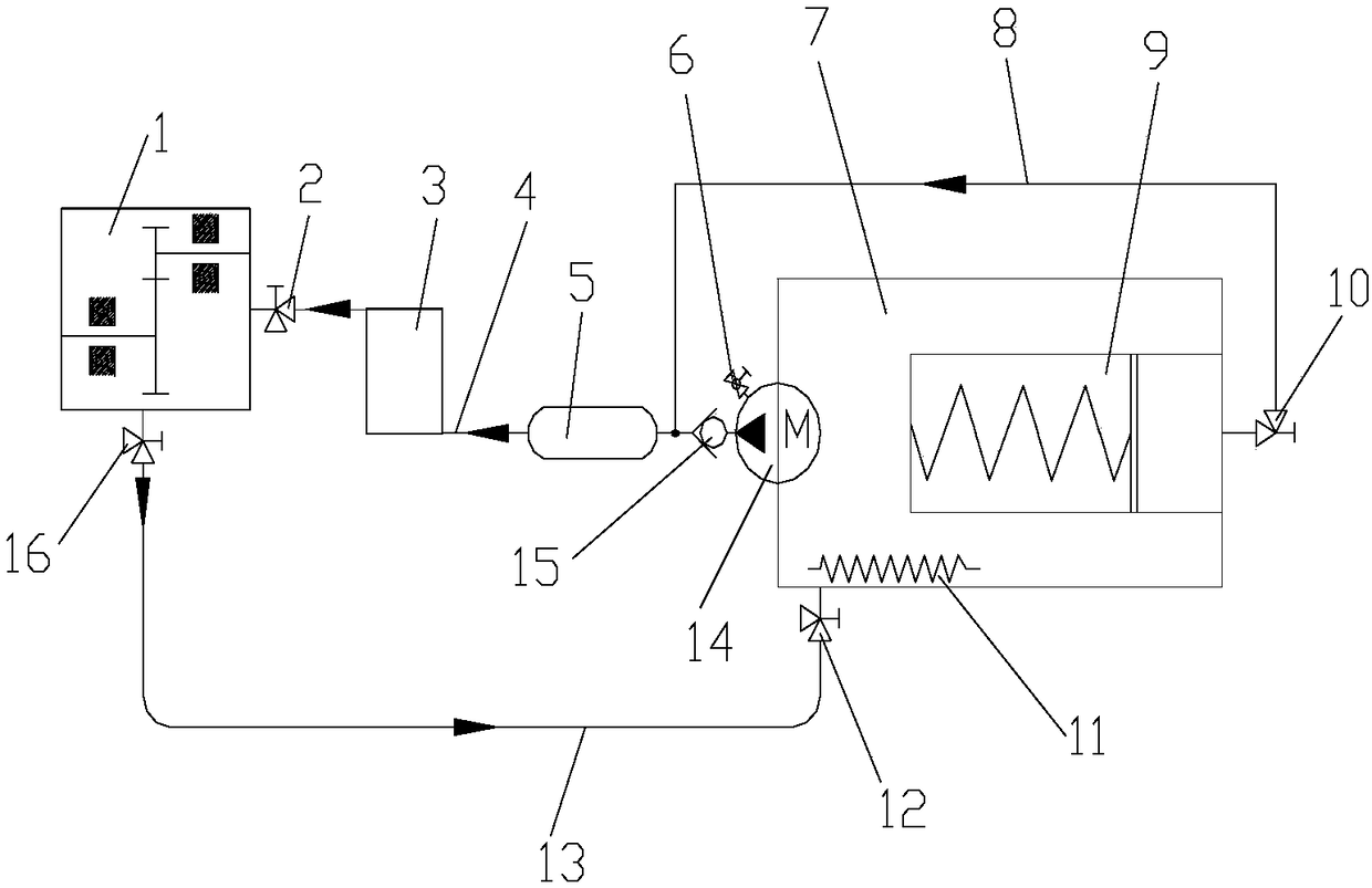
[0004] The technical problem to be solved by the present invention is to provide a lubricating oil supply protection device for a gear transmission mechanism. The present invention solves the problem that lubricating oil cannot be provided to lubricate the mechanism bearings and gear pairs when the oil pump stops running

Method used


Image

  • Lubrication oil supply protection device for gear transmission mechanism
  • Lubrication oil supply protection device for gear transmission mechanism
  • Lubrication oil supply protection device for gear transmission mechanism

Examples


Embodiment 1

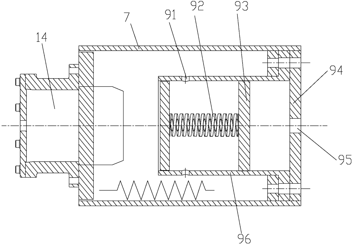
[0021] The oil tank 7 is placed horizontally in a cylindrical shape, and an oil pump 14 is installed on the left end surface of the oil tank 7, and the oil pump 14 is equipped with a pressure regulating valve 6 for regulating the pressure of the pipeline. An oil heater 11 (Taiyi Thermal Electric Appliance Company-QY380-PT1-3023) for heating lubricating oil is installed on the bottom of the inner cavity of the oil tank 7, and a pressure oil storage chamber coaxial with the oil tank 7 is installed on the right end surface of the oil tank 7 9. The pressure oil storage chamber 9 includes a barrel-shaped chamber 96, a piston 93 arranged in the chamber 96, a spring 92 fixed at the bottom of the chamber 96 and the piston 93 at both ends, and an end arranged at the port of the chamber 96. The cover 94 and the end cover 94 are provided with an oil outlet 95 . The outlet of the oil pump 7 (Chongqing Yimei Machinery Complete Equipment Co., Ltd.-LSQYB60-80) is connected to the lubricatin...

Embodiment 2

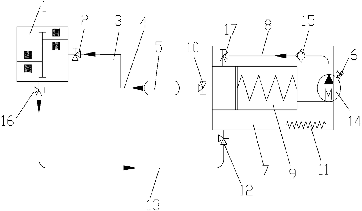
[0024] On the basis of Example 1, such as figure 2 As shown, the bypass oil supply circuit 8 is set in the oil tank 7, the outlet of the oil pump 14 is connected to the bypass oil pipeline 8, the other end of the bypass oil pipeline 8 passes through the fifth regulating valve 17 and the pressure oil storage chamber 9, and the bypass oil pipeline 8 A one-way valve 15 is provided, and the oil outlet 95 of the pressure oil storage chamber 9 is connected with the main oil supply circuit 4 through the third regulating valve 10 .

[0025] When the gear transmission mechanism operates normally, the oil pump 14 works normally, the first regulating valve 2, the second regulating valve 10, the third regulating valve 16, the fourth regulating valve 12, and the fifth regulating valve 17 are all opened, and the oil pump 14 continues to run. The oil supply pressure is adjusted through the pressure regulating valve 6, the fifth regulating valve 17, the third regulating valve 10, and the fir...


PUM


Abstract

The invention discloses a lubrication oil supply protection device for a gear transmission mechanism, and relates to the field of lubrication protection devices. The lubrication oil supply protectiondevice for the gear transmission mechanism comprises an oil tank, an oil pump connected with the oil tank, and a pressure oil storage cavity arranged in an inner cavity of the oil tank. An outlet of the oil pump is connected with a lubricating oil injection port of the gear transmission mechanism through a main oil supply circuit and a first stop valve sequentially; a lubricating oil discharge hole of the gear transmission mechanism is connected with the oil tank through an oil return circuit; an oil outlet of a pressure oil storage cavity is connected with the lubricating oil injection port of the gear transmission mechanism through a second stop valve, a by-pass oil supply circuit and the first stop valve sequentially; the pressure oil storage cavity comprises a barrel-shaped cavity body, a piston arranged in the cavity body, a spring with two ends being fixed onto the bottom surface of the cavity body and the piston, and an end cover arranged on the end port of the cavity body; andan oil outlet is formed in the end cover. The lubrication oil supply protection device for the gear transmission mechanism provided by the invention solves the problem that when the oil pump stops running, the oil pump cannot provide lubricating oil to lubricate a gear set.

Description

technical field [0001] The invention relates to the field of lubrication protection devices, in particular to a lubrication oil supply protection device for a gear transmission mechanism. Background technique [0002] As we all know, the gear transmission mechanism is generally divided into a gear speed-up mechanism and a speed-down mechanism. It is a mechanism that adjusts the actual output speed according to needs. Composed of driven components and forced circulation oil supply lubrication system. [0003] Generally, the forced circulation oil supply system is composed of oil tank, oil heater, oil pump, pressure regulating valve, oil filter, oil cooler and so on. Under normal circumstances, when the gear transmission mechanism is running, the forced circulation oil supply system continuously supplies oil to the bearings, gears, etc. to ensure lubrication and cooling, but when the mechanism fails or the oil pump is abnormal, or other irresistible external forces When the ...

Claims


Application Information

Patent Timeline
Patent Type & Authority Applications(China)
IPC IPC(8): F16H57/04F16N7/38F16N39/04F16N39/06F16N23/00
CPCF16H57/0413F16H57/0434F16N7/38F16N23/00F16N39/04F16N39/06F16N2210/12
Inventor 赵文骐
Owner 赵文骐
Learn More