
Optimized single-side air inlet induced draft tower

A fan, side entry technology, applied in the direction of water shower cooler, direct contact heat exchanger, heat exchanger type, etc., can solve the waste of filling area in the water spray area in the tower, the mechanical tower is difficult to achieve cooling effect, disadvantageous Cooling tower intake air balance configuration and other issues, to achieve the effect of reducing coal consumption or steam consumption, increasing width, and improving heat transfer performance

Active Publication Date: 2018-09-28
CHINA ENERGY ENG GRP GUANGDONG ELECTRIC POWER DESIGN INST CO LTD
View PDF4 Cites 3 Cited by
  • Summary
  • Abstract
  • Description
  • Claims
  • Application Information

AI Technical Summary

Problems solved by technology

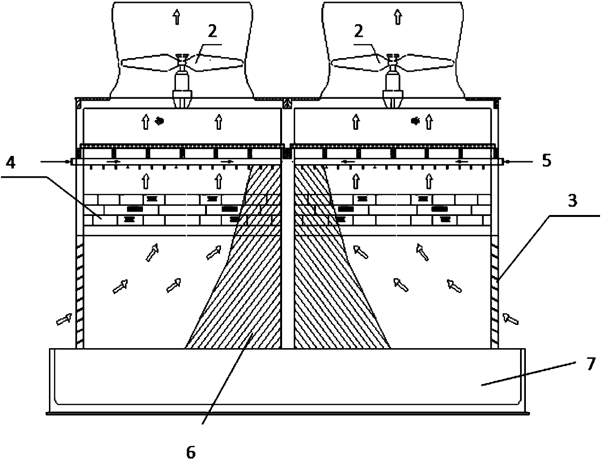
However, the power tower with one-sided air intake has an obvious air intake dead zone 6, which greatly reduces the cooling performance of the power tower
[0004] The layout of the power tower with one-sided air intake is not conducive to the balanced configuration of the air intake of the cooling tower. The water spraying area and the filling area in the tower cause a large waste. Therefore, in some seasons, especially in summer, the power tower is difficult to achieve the expected cooling. As a result, the tower water temperature is too high, and the cooling effect of some measured items deviates from the design value by about 1 to 1.5 degrees

Method used


Image

  • Optimized single-side air inlet induced draft tower
  • Optimized single-side air inlet induced draft tower
  • Optimized single-side air inlet induced draft tower

Examples


Embodiment Construction

[0023] The present invention will be further described in detail below in conjunction with the embodiments and the accompanying drawings, but the embodiments of the present invention are not limited thereto.

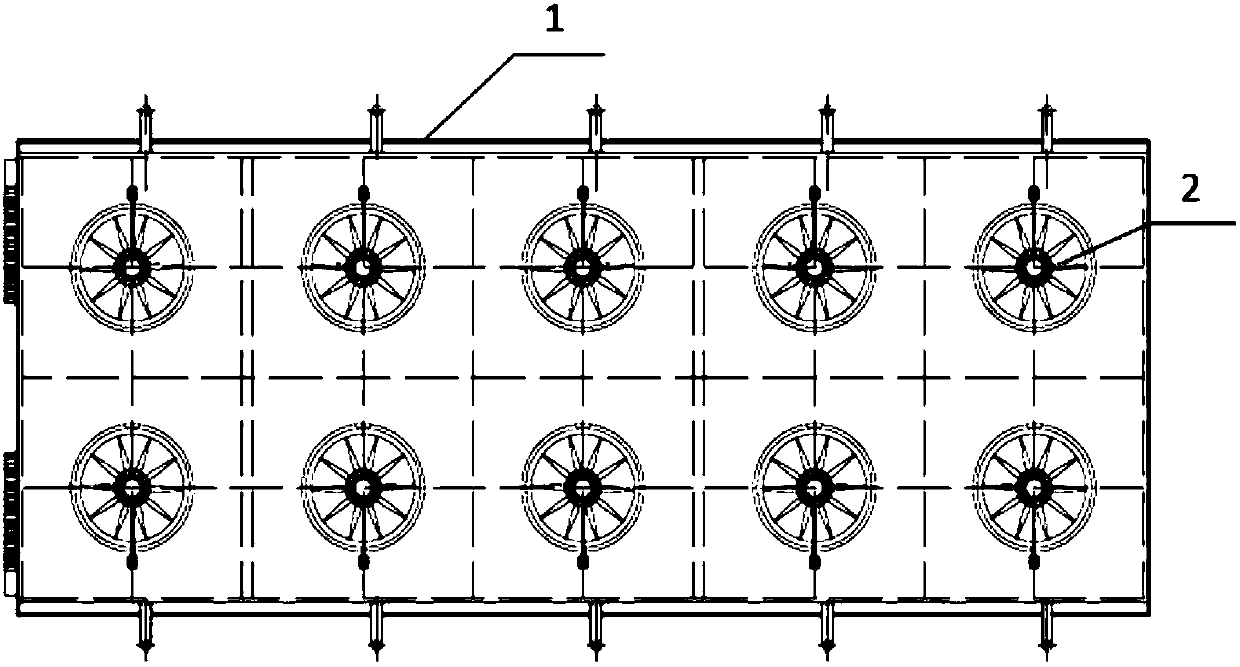
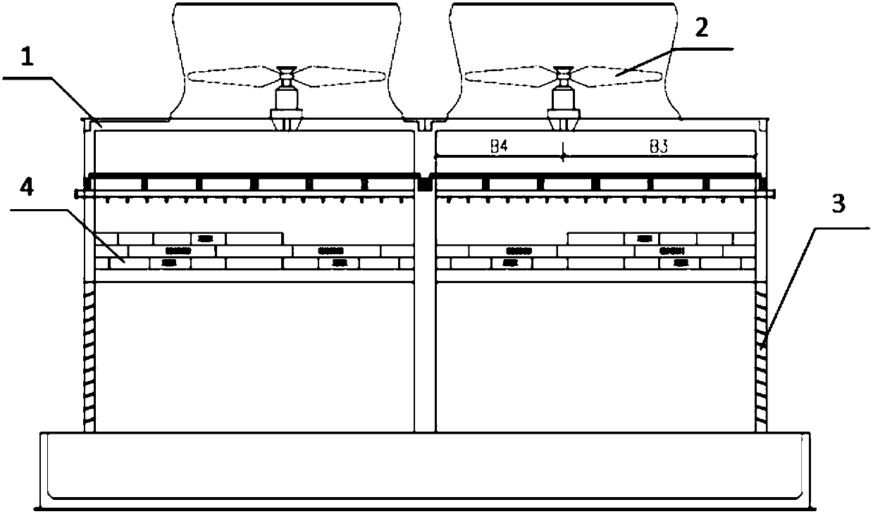
[0024] Such as image 3 As shown, the embodiment of the present invention provides an optimized single-side wind inlet power tower, the power tower includes a tower body 1 , a fan 2 and packing 4 , and the tower body is provided with an air inlet 3 . Because the wind enters the power tower from one side, after the wind enters the power tower from the air inlet 3, it will form a windward side and a leeward side in the tower, so the filler 4 can be divided into a windward side filler and a leeward side filler.

[0025] The fan 2 of the conventional power tower is arranged at the very center of the tower, that is, the distance from the centerline of the fan 2 to the inner walls on both sides of the power tower is equal. With the arrangement of the fan 2 in this form, when ...


PUM


Abstract

The invention discloses an optimized single-side air inlet induced draft tower. The induced draft tower comprises a tower body, fans and padding. An air inlet is formed in the tower body. The paddingis divided into a windward side padding body and a leeward side padding body. The distance between the center lines of the fans and the windward side inner wall surface of the tower body is B3, and the distance between the center lines of the fans and the leeward side inner wall surface of the tower body is B4 (please see the ratio of B3 to B4 in the specification). By optimizing the parameters such as the fan arrangement position, the height of the air inlet, the height and width of the padding and the water spraying density, the inlet air dead zone is reduced, and the inlet air in the toweris optimized; and the cooling effect of a rain area and the padding in the tower is fully utilized, so that the cooling performance of the entire induced draft tower is improved.

Description

technical field [0001] The invention relates to the technical field of mechanical ventilation cooling towers, in particular to an optimized single-side air intake mechanical ventilation counterflow cooling tower. Background technique [0002] The mechanical ventilation counterflow cooling tower (referred to as the mechanical tower) is a cooling tower that relies on forced ventilation of the fan to cool the water. The mechanical draft cooling tower is currently the most widely used cooling tower. When the number of cells of the power tower is large, it is generally arranged in multiple rows. When the tower rows are arranged with a distance between them, it is a double-sided air intake cooling tower. When the land occupation of some projects is limited and the site layout is tense, the cooling tower rows will be arranged back to back, and at this time it is a single-side air inlet cooling tower. The air inlets on both sides of the double-sided air intake tower can enter the ...

Claims


Application Information

Patent Timeline
IPC IPC(8): F28C1/00F28F25/08F28F25/12
CPCF28C1/00F28F25/08F28F25/12
Inventor 杨志龙国庆毛卫兵李波
Owner CHINA ENERGY ENG GRP GUANGDONG ELECTRIC POWER DESIGN INST CO LTD
Learn More