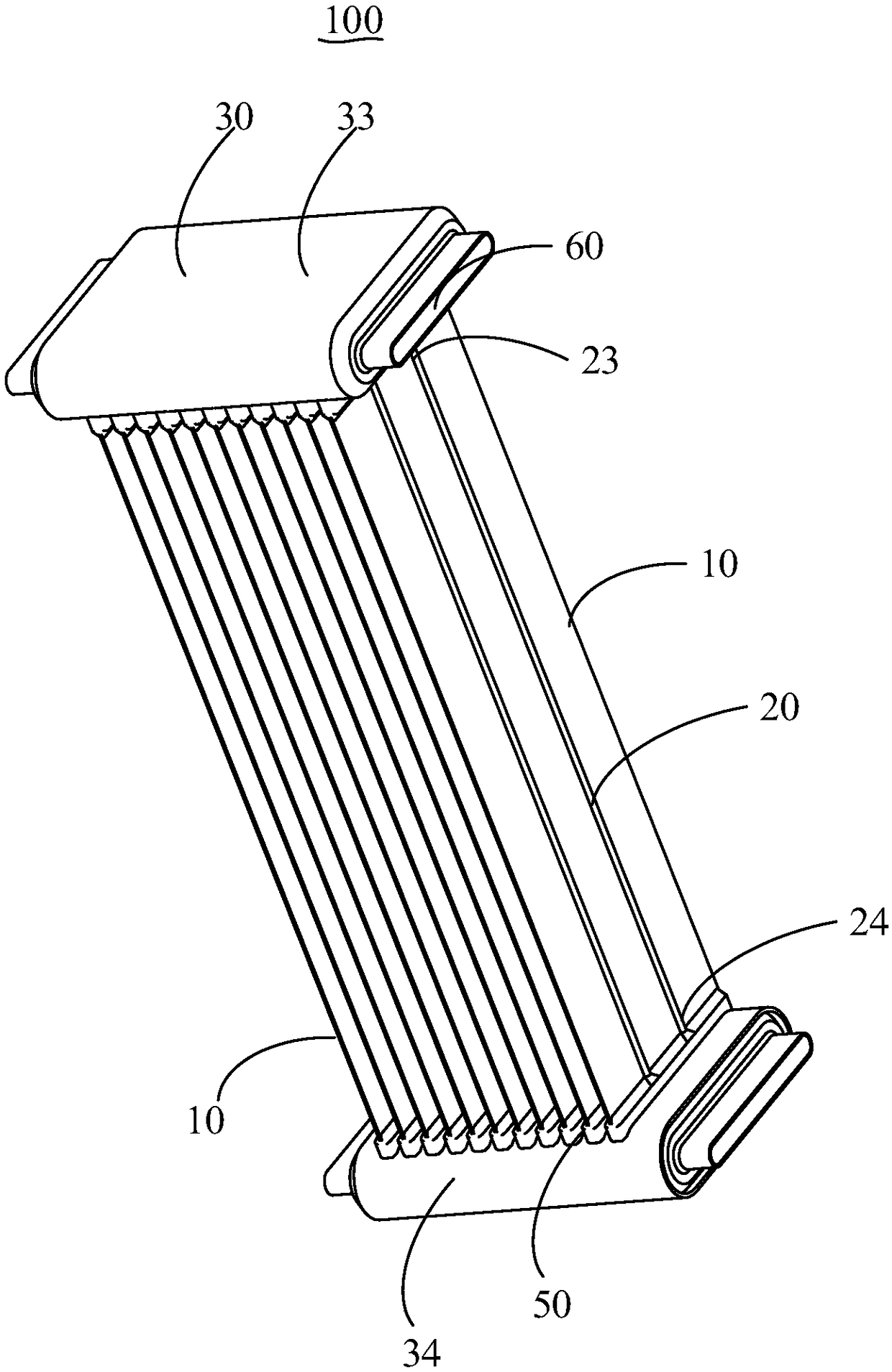
Heat exchanger and heat exchange equipment

A heat exchange equipment and heat exchanger technology, which is applied in the field of heat exchangers, can solve the problems of large heat exchanger space and unfavorable miniaturization of heat exchangers, so as to increase heat exchange area, improve heat exchange and heat exchange. Efficient, easy to make effects

Pending Publication Date: 2018-09-28
GD MIDEA AIR-CONDITIONING EQUIP CO LTD +1
View PDF8 Cites 4 Cited by
  • Summary
  • Abstract
  • Description
  • Claims
  • Application Information

AI Technical Summary

Problems solved by technology

[0003] The main purpose of the present invention is to provide an air outlet channel, aiming to solve the problem in the prior art that the header takes up too much space in the heat exchanger, which is not conducive to miniaturization of the heat exchanger

Method used


Image

  • Heat exchanger and heat exchange equipment
  • Heat exchanger and heat exchange equipment
  • Heat exchanger and heat exchange equipment

Examples


Embodiment Construction

[0041] The following will clearly and completely describe the technical solutions in the embodiments of the present invention with reference to the accompanying drawings in the embodiments of the present invention. Obviously, the described embodiments are only part of the embodiments of the present invention, not all of them. Based on the embodiments of the present invention, all other embodiments obtained by persons of ordinary skill in the art without creative efforts fall within the protection scope of the present invention.

[0042] It should be noted that all directional indications (such as up, down, left, right, front, back...) in the embodiments of the present invention are only used to explain the relationship between the components in a certain posture (as shown in the accompanying drawings). Relative positional relationship, movement conditions, etc., if the specific posture changes, the directional indication will also change accordingly.

[0043] In addition, the ...


PUM


Abstract

The invention provides a heat exchanger and heat exchange equipment. The heat exchanger comprises a plurality of fins, heat exchange tubes and an unilateral collecting flow tube, wherein the pluralityof fins are arranged at intervals, the heat exchange tubes extends to the surfaces of the fins or are formed in the fins, and the heat exchange tubes are arranged in a buckling and folding shape; theunilateral collecting flow tube is arranged at one end in the length directions of the fins, the unilateral collecting flow tube comprises an inflow passage and an outflow passage, wherein the inflowchannel and the outflow channel are arranged at the two ends in the width direction of the fins correspondingly; and the two ends of the heat exchange tubes correspondingly communicate with the inflow channel and the outflow channel. According to the heat exchanger and the equipment, the heat exchanger and the heat exchange equipment has the advantages of being compact in structure, high in heatexchange, high in heat exchange efficiency and capable of realizing miniaturization design of the heat exchanger.

Description

technical field [0001] The invention relates to the technical field of heat exchangers, in particular to a heat exchanger and heat exchange equipment. Background technique [0002] In the prior art, the header of the heat exchanger generally includes a refrigerant inflow pipe and a refrigerant outflow pipe. The heat exchange pipe is connected with the refrigerant inflow pipe and the refrigerant outflow pipe. The refrigerant flows out through the refrigerant inflow pipe and the heat exchange pipe from the refrigerant outflow pipe. , so the refrigerant inflow pipe and the refrigerant outflow pipe are generally distributed on both sides of the heat exchange tube to facilitate the circulation of the refrigerant, but the refrigerant inflow pipe and the refrigerant outflow pipe are distributed on both sides of the heat exchange tube, causing the header to occupy too much space in the heat exchanger , is not conducive to the miniaturization of the heat exchanger. Contents of the ...

Claims


Application Information

Patent Timeline
Patent Type & Authority Applications(China)
IPC IPC(8): F28D1/04F28F1/12F28F9/02F28F21/02F25B39/02
CPCF25B39/02F25B2339/023F28D1/04F28F1/12F28F9/02F28F21/02F28F2245/04
Inventor 北本学武滔陈新厂
Owner GD MIDEA AIR-CONDITIONING EQUIP CO LTD
Why Eureka
Try Eureka