Detection device for detecting verticality of bridge pier

A detection device and verticality technology, which is applied in the measurement of fixed angles and other directions, can solve the problems of low data accuracy and measurement error, and achieve the effects of extending service life, reducing wear and reducing friction.

Active Publication Date: 2018-09-28
ZHEJIANG JIAOKE ENG TESTING
View PDF3 Cites 0 Cited by
  • Summary
  • Abstract
  • Description
  • Claims
  • Application Information

AI Technical Summary

Problems solved by technology

[0007] In actual detection, the accuracy of the data that can be read

Method used


Image

  • Detection device for detecting verticality of bridge pier
  • Detection device for detecting verticality of bridge pier
  • Detection device for detecting verticality of bridge pier

Examples


Example Embodiment

[0041] Example one:

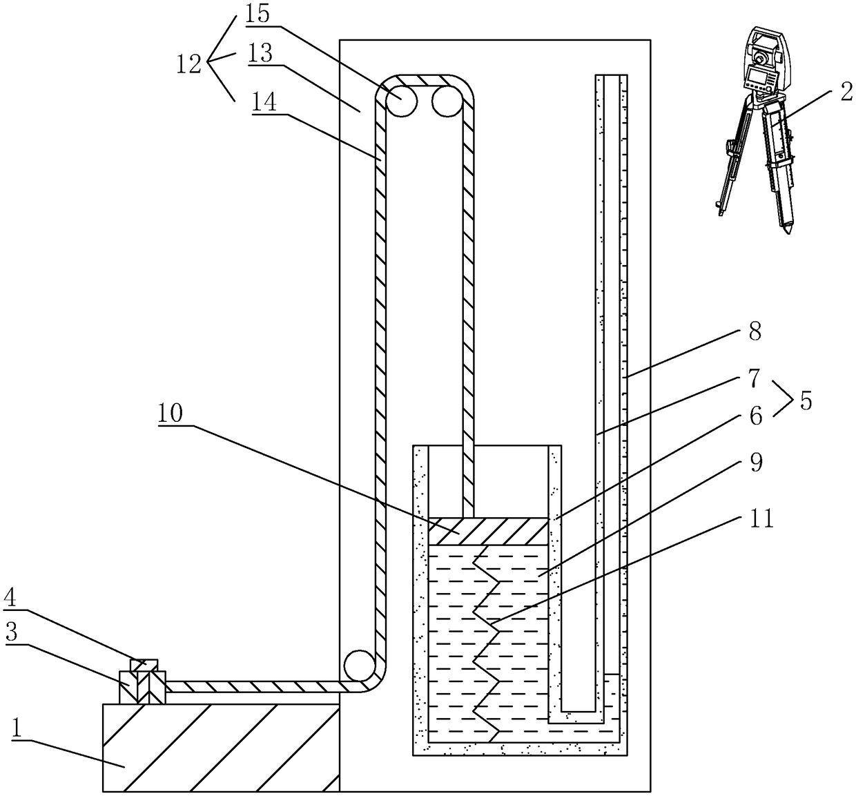
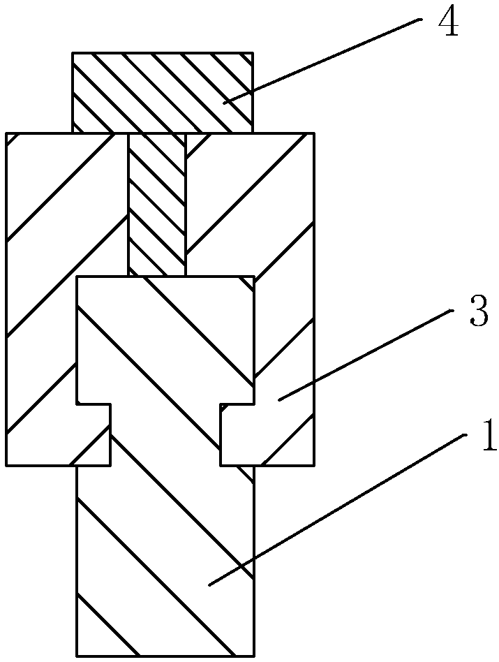
[0042] Such as figure 1 As shown, a detection device for verticality detection of bridge piers includes a straight rod 1 and a total station 2. Such as figure 1 with figure 2 As shown, the sliding sleeve on the straight rod 1 is provided with a sliding sleeve 3, and the sliding sleeve 3 is threaded with a fixing bolt 4. When the fixing bolt 4 is screwed until it abuts the straight rod 1, the sliding sleeve 3 is fixed relative to the straight rod 1.

[0043] Such as figure 1 As shown, one side of the straight rod 1 is provided with a reading amplifying assembly 5, which can amplify the distance that the sliding sleeve 3 moves relative to the straight rod 1. The reading amplifying assembly 5 includes a liquid storage area 6 and a reading area 7. The reading area 7 is provided with a scale line 8 for reflecting the movement distance of the sliding sleeve 3. The liquid storage area 6 and the reading area 7 are both tubular and arranged in a vertical direction. ...

Example Embodiment

[0053] Embodiment two:

[0054] Such as Figure 4 As shown, the difference between the second embodiment and the first embodiment is that the liquid storage area 6 is arranged in a vertical direction, the reading area 7 is arranged in an arc with the opening facing upward, and the lower end of the reading area 7 is connected to the lower end of the liquid storage area 6.

[0055] The circular arc setting of the reading area 7 reduces the height of the reading area 7 in the vertical direction, reduces the total volume of the device, and is more convenient for users to read.

Example Embodiment

[0056] Embodiment three:

[0057] Such as Figure 5 As shown, the difference between the third embodiment and the first embodiment is that the liquid storage area 6 is arranged in the vertical direction, and the reading area 7 is arranged in the horizontal direction. A reading block 18 is slidably embedded in the reading area 7, and the measuring liquid 9 is located between the reading block 18 and the sliding block 10. The reading block 18 abuts on the inner wall of the reading area 7 and can slide relative to the reading area 7. An elastic member 17 for resetting the reading block 18 is provided on the side of the reading block 18 opposite to the liquid storage area 6. The elastic member 17 can be a spring, an elastic rope, or the like. The elastic member 17 is parallel to the reading area 7, and both ends of the elastic member 17 are fixedly connected to the reading block 18 and the frame 13 respectively. When the elastic member 17 is in a natural state, the slider 10 is lo...


PUM


Abstract

The invention relates to detection of bridge piers, and particularly discloses a detection device for detecting verticality of a bridge pier. The detection device comprises a straight rod and a totalstation, wherein a slide sleeve is positioned and glidingly sheathes the straight rod; a reading amplifying assembly is arranged at one side of the straight rod, and comprises a liquid storage area and a reading area which is communicated with the liquid storage area; the liquid storage area and the reading area are respectively in a tube shape, the cross section of the liquid storage area is greater than the cross section of the reading area, and measuring liquids are loaded into the liquid storage area and the reading area; a slide block is glidingly embedded into the liquid storage area; the slide block is abutted against the inner wall of the liquid storage area; a reset part is arranged between the slide block and the liquid storage area, and is used for resetting the slide block to one end, near the reading area, of the liquid storage area; a reversing mechanism is arranged between the slide block and the slide sleeve, and is used for converting the movement pair of the slide sleeve along the straight rod into the axial movement pair of the slide block along the liquid storage area. The detection device has the advantage that when the slide sleeve is moved each time, the liquid level of the reading area is greatly changed, so that a measurer can more precisely obtain the deviation of the verticality.

Description

technical field [0001] The invention relates to the technical field of bridge pier detection, in particular to a detection device for detecting the verticality of bridge piers. Background technique [0002] For a long time, it has been a difficult problem to detect the verticality of pier columns. Now the method of total station plus ruler is generally used. The specific steps of the detection are as follows: [0003] 1. Set up the total station to the position where the complete pier column can be seen; [0004] 2. First adjust the viewing angle of the instrument to the outermost side of the pier column top formwork, and then lock the horizontal plate; [0005] 3. Use a straightedge to place vertically on the outside of the bottom of the corresponding pier formwork; [0006] 4. Adjust the viewing angle of the total station to the bottom of the template, read the ruler data directly, and obtain the vertical deviation of the pier. [0007] In actual detection, the accurac...

Claims


Application Information

Patent Timeline
IPC IPC(8): G01C15/12
CPCG01C15/12
Inventor 李奎宋景景项超王炎余华燕徐晓熙高强邱东波
Owner ZHEJIANG JIAOKE ENG TESTING
Why Eureka
Try Eureka