Double-telecentric optical detection device with variable multiplying power

An optical detection and bi-telecentric technology, applied in the field of optical detection, can solve the problem that the bi-telecentric optical detection system cannot be used to detect samples of different sizes at the same time, and achieve the effect of fast real-time detection

Inactive Publication Date: 2018-09-28
宾努克斯科技(佛山)有限公司
View PDF6 Cites 4 Cited by
  • Summary
  • Abstract
  • Description
  • Claims
  • Application Information

AI Technical Summary

Problems solved by technology

[0005] The embodiment of the present invention provides a variable magnification bi-telecentric optical detection device to solve the

Method used


Image

  • Double-telecentric optical detection device with variable multiplying power
  • Double-telecentric optical detection device with variable multiplying power
  • Double-telecentric optical detection device with variable multiplying power

Examples


Example Embodiment

[0017] The technical solutions in the embodiments of the present invention will be clearly and completely described below in conjunction with the accompanying drawings in the embodiments of the present invention. Obviously, the described embodiments are part of the embodiments of the present invention, not all of them. Based on the embodiments of the present invention, all other embodiments obtained by those of ordinary skill in the art without creative work shall fall within the protection scope of the present invention.
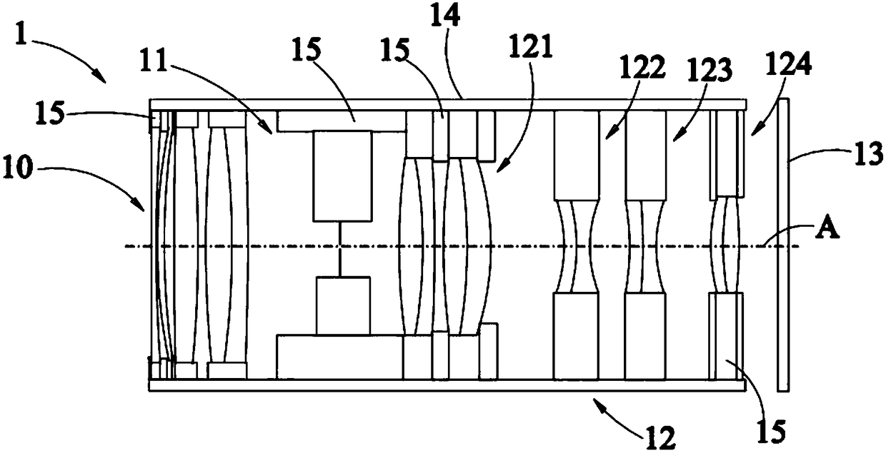
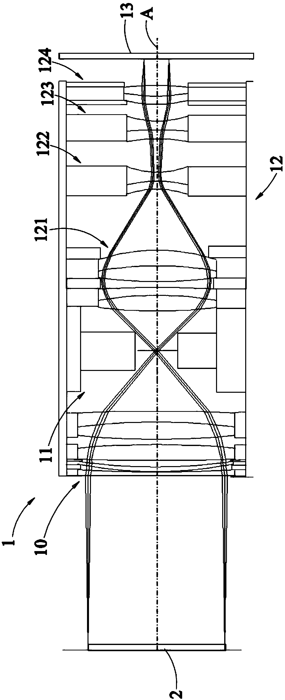
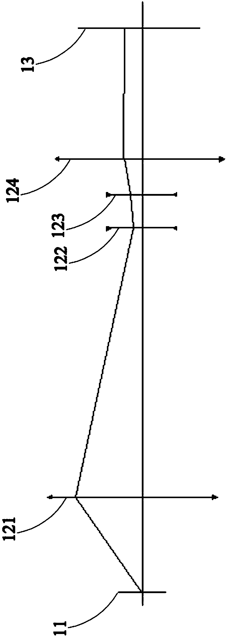
[0018] See figure 1 , Which is a schematic diagram of the bi-telecentric optical detection device of the first embodiment of the present invention; as shown in the figure, the variable magnification bi-telecentric optical detection device 1 of this embodiment includes an objective lens group 10, a diaphragm 11, and an eyepiece group 12 and the imaging element 13, the objective lens group 10, the diaphragm 11 and the eyepiece group 12 are all arranged in the len...


PUM


Abstract

The invention discloses a double-telecentric optical detection device with variable multiplying power. The double-telecentric optical detection device comprises an objective lens group, a diaphragm, an eye lens group and an imaging element. The objective lens group and the eye lens group are arranged on two sides of the diaphragm, the imaging element is arranged on a side of the eye lens group andis opposite to the diaphragm, the eye lens group comprises a first optical lens group, a optical lens group with variable multiplying power, a compensating optical lens group and a second optical lens group, the first optical lens group, the optical lens group with the variable multiplying power, the compensating optical lens group and the second optical lens group are sequentially arrayed from the diaphragm to the imaging element, and the optical lens group with the variable multiplying power and the compensating optical lens group can move relative to the first optical lens group and the second optical lens group, so that the focal power of the eye lens group can be changed. The double-telecentric optical detection device has the advantages that the optical lens group with the variablemultiplying power and the compensating optical lens group of the eye lens group can be adjusted according to to-be-tested objects with different sizes, accordingly, the continuous zooming purpose canbe achieved, the to-be-tested objects with the different sizes can be quickly detected by the double-telecentric optical detection device in real time, and cross-scale measurement effects can be realized by the double-telecentric optical detection device.

Description

technical field [0001] The invention relates to the technical field of optical detection, in particular to a double telecentric optical detection device with variable magnification. Background technique [0002] In the field of machine vision, if the optical inspection equipment uses a non-object telecentric structure, once the object distance changes, the magnification will change accordingly, which will be affected in the use environment in industrial inspection, and it is difficult to guarantee the accuracy of inspection. Accuracy requires strict control of the object distance, and a small defocus will affect the normal operation of the system. The general non-image square telecentric structure, in the variable magnification system, the position of the charge-coupled device (CCD) is fixed, and the inaccurate image square focus will bring measurement errors, and the structure is complicated when the zoom magnification is high . [0003] Under the bi-telecentric structure...

Claims


Application Information

Patent Timeline
IPC IPC(8): G02B25/00G02B13/22
CPCG02B13/22G02B25/001
Inventor 王和云孙顺平
Owner 宾努克斯科技(佛山)有限公司
Why Eureka
Try Eureka