
Fuel measurement sensor layout optimization method for aircraft fuel tank

A technology of measuring sensor and fuel quantity sensor, applied in the field of aircraft fuel tank fuel quantity measuring system, which can solve the problems of troublesome fuel model, unsuitable for wing flat fuel tank structure, lack of sensors, etc.

Active Publication Date: 2018-09-28
XI AN JIAOTONG UNIV
View PDF3 Cites 3 Cited by
  • Summary
  • Abstract
  • Description
  • Claims
  • Application Information

AI Technical Summary

Problems solved by technology

[0002] At present, domestic aircraft fuel tank fuel measurement sensor layout optimization methods mainly focus on the face-centered arrangement method of a single sensor and the symmetrical face-centered arrangement method of multiple sensors for the characteristics of slender or regular fuel tanks, but its disadvantage is that it is not suitable for the wings widely used in modern aircraft. Flat tank structure
In the actual model, the layout of sensors for irregular fuel tank structures mainly depends on the work experience of engineers, which generally cannot obtain the optimal layout results, and the workload of designers is greatly increased, and the development cycle is lengthened
At the same time, there is a lack of good sensor layout optimization design methods. The existing design methods are based on the relevant functions in commercial CAD software. Due to the complex structure of modern aircraft fuel tanks, there are also some conduits and pumps of various shapes and sizes inside the fuel tank. , valves and other components, in commercial CAD software, it is very troublesome to accurately obtain the fuel model for sensor layout optimization, and with the increase of model complexity in the layout optimization process, commercial CAD software has high memory requirements, Moreover, mistakes are often made during operation, which seriously affects design efficiency. It is necessary to develop design methods independent of commercial CAD software for layout optimization.

Method used


Image

  • Fuel measurement sensor layout optimization method for aircraft fuel tank
  • Fuel measurement sensor layout optimization method for aircraft fuel tank
  • Fuel measurement sensor layout optimization method for aircraft fuel tank

Examples


Embodiment Construction

[0051] The present invention will be described in detail below in conjunction with the accompanying drawings and specific embodiments, where the schematic embodiments and descriptions of the present invention are used to explain the present invention, but not to limit the present invention.

[0052] The layout optimization method of the aircraft fuel tank fuel measuring sensor of the present invention comprises:

[0053] Step 1) Firstly, generate the bottom initialization arrangable area, that is, the arranging full set.

[0054] In the early stage of fuel system design, usually the pipelines, pumps, valves, openings and other related information in the fuel tank have not been added, and all areas at the bottom can be used as the initial layout area; When the complexity makes it impossible to arrange the sensors, this part of the surface may not be extracted.

[0055] 1.1), first generate discrete points in the feasibility area of ​​the bottom of the fuel tank;

[0056] 1.2)...


PUM


Abstract

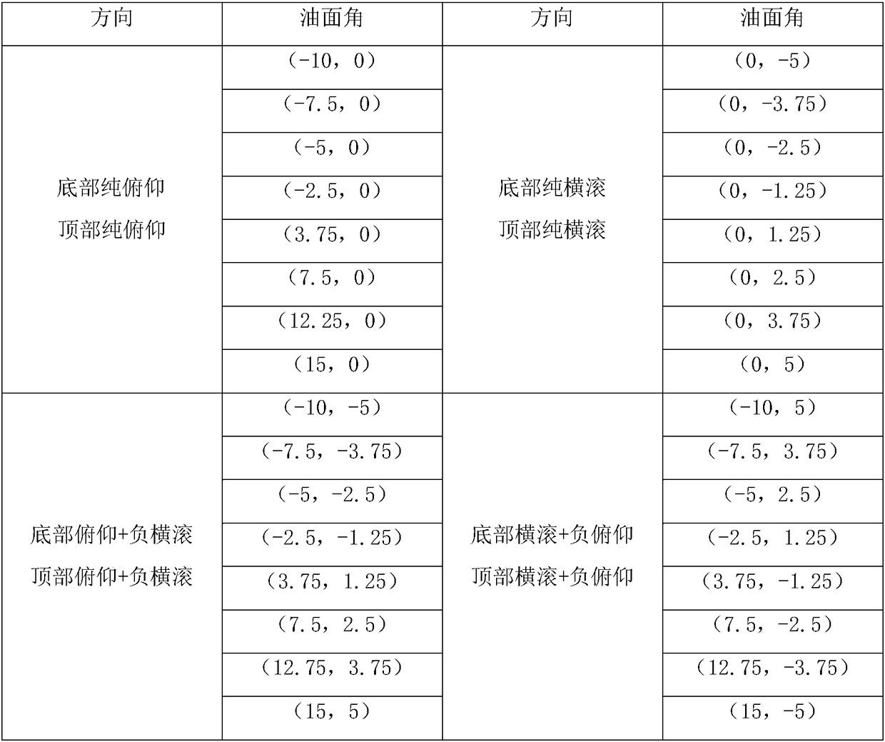
The invention discloses a fuel measurement sensor layout optimization method for an aircraft fuel tank. The method comprises the steps of generating an initialized arrangement region of the fuel tank;dividing different fuel surface attitude angles; screening out sensor installation wire sets meeting bottom and top non-measurable fuel capacity constraints under the different fuel surface attitudeangles; combining the sensor installation wire sets accordingly, and arranging the combined sensor installation wire sets according to the quantities from small to large, thereby obtaining different quantities of sensor installation wire combinations; and traversing different sensor installation wire combinations, performing continuity judgment and attitude error judgment on the sensor installation wire combinations, and selecting the minimal quantity of the sensor installation wire combinations meeting continuity constraints and attitude error constraints as a fuel capacity sensor layout optimization result. According to the method, an optimal sensor layout can be obtained on the basis of meeting design precision requirements; and meanwhile, sensors arranged by designers can be subjectedto design precision verification, thereby ensuring the sensors to meet the design requirements.

Description

technical field [0001] The invention belongs to the field of aircraft fuel tank fuel oil quantity measurement systems, and relates to a layout optimization method of aircraft fuel tank fuel oil measurement sensors. Background technique [0002] At present, domestic aircraft fuel tank fuel measurement sensor layout optimization methods mainly focus on the face-centered arrangement method of a single sensor and the symmetrical face-centered arrangement method of multiple sensors for the characteristics of slender or regular fuel tanks, but its disadvantage is that it is not suitable for the wings widely used in modern aircraft. Flat fuel tank structure. In the actual model, the layout of sensors for irregular fuel tank structures mainly depends on the work experience of engineers, which generally cannot obtain the optimal layout results, and the workload of designers is greatly increased, and the development cycle is lengthened. At the same time, there is a lack of good senso...

Claims


Application Information

Patent Timeline
Patent Type & Authority Applications(China)
IPC IPC(8): G06F17/50
CPCG06F30/20G06F2111/04
Inventor 郑帅李宝童杨拓洪军
Owner XI AN JIAOTONG UNIV
Learn More