Check patentability & draft patents in minutes with Patsnap Eureka AI!

Virtual reality image display method and terminal based on micro-spacing LED display screen

A LED display and virtual reality technology, applied in the field of virtual reality, can solve problems such as inability to display images, poor product versatility, and automatic scaling of brightness, so as to improve practicability and versatility, diversify display images, and improve user experience Effect

Active Publication Date: 2018-09-28
UNILUMIN GRP
View PDF8 Cites 1 Cited by
  • Summary
  • Abstract
  • Description
  • Claims
  • Application Information

AI Technical Summary

Problems solved by technology

When the viewing distance of the experiencer changes, the automatic scaling of the display screen and the automatic adjustment of the display brightness cannot be performed, which will not only affect the experience effect, but also cause problems such as high energy consumption and poor product versatility.

Method used


Image

  • Virtual reality image display method and terminal based on micro-spacing LED display screen
  • Virtual reality image display method and terminal based on micro-spacing LED display screen
  • Virtual reality image display method and terminal based on micro-spacing LED display screen

Examples


Embodiment 1

[0058] Please refer to figure 1 and figure 2 , Embodiment 1 of the present invention is:

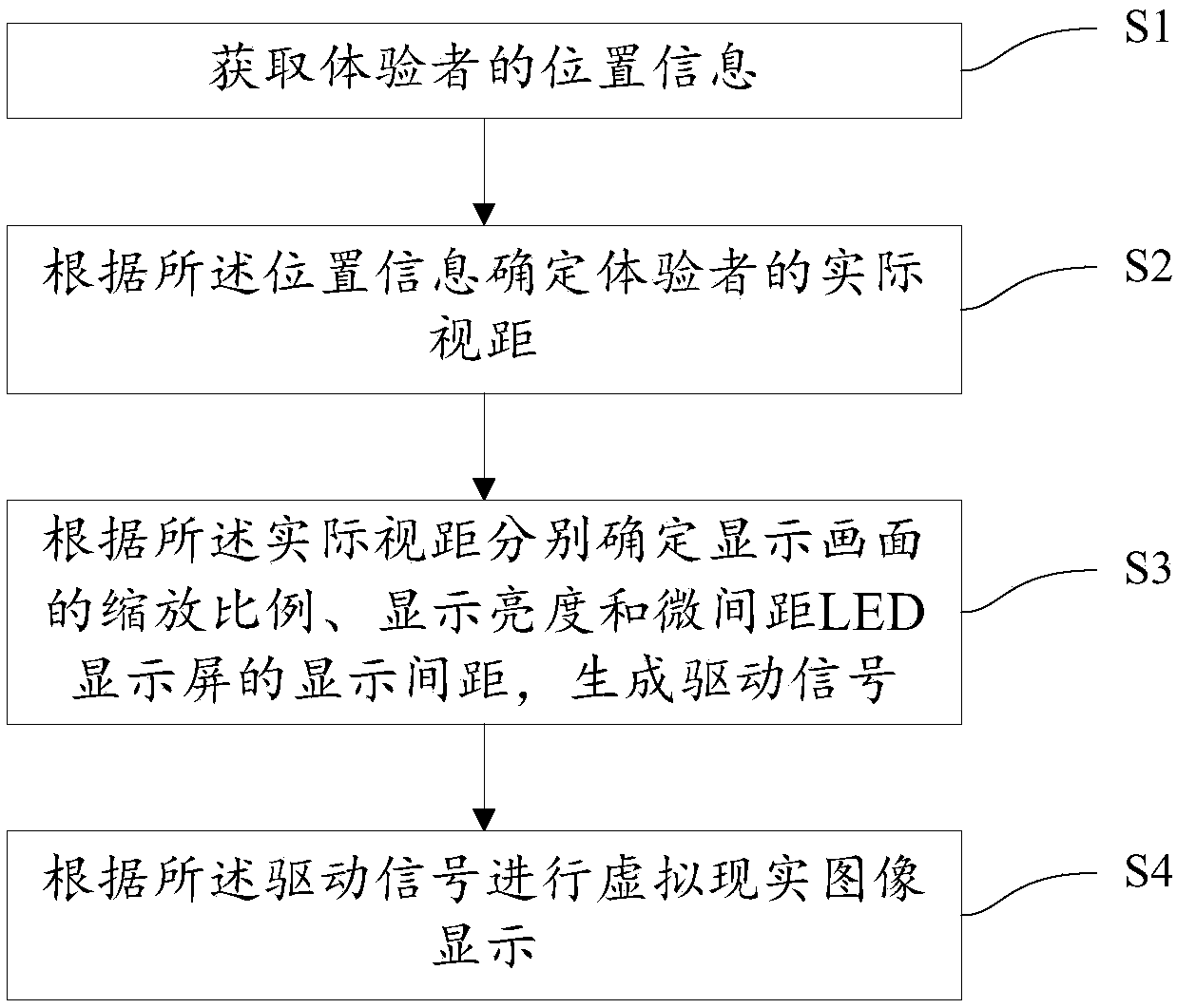
[0059] A kind of virtual reality image display method based on micro-pitch LED display screen, such as figure 1 shown, including:

[0060] S1. Obtain the location information of the experiencer. The location information of the experiencer can be collected by a pressure sensor, or by an image sensor, and of course, can also be determined by combining the pressure sensor and the image sensor. In this embodiment, location information can also be input by setting the data input information system, and different location information data can be input as required.

[0061] S2. Determine the actual viewing distance of the experiencer according to the location information. The distance between the experiencer and the LED display is different, and the actual viewing distance is different.

[0062] S3. Determine the zoom ratio of the display screen, the display brightness, and the display pit...

Embodiment 2

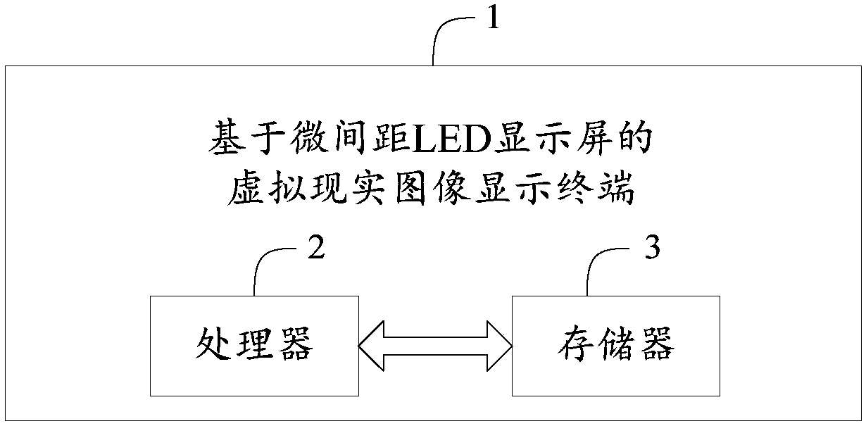
[0067] Please refer to image 3 , the second embodiment of the present invention is:

[0068] A virtual reality image display terminal 1 based on a micro-pitch LED display screen, corresponding to the method in Embodiment 1, including a processor 2, a memory 3, and a computer program stored in the memory 3 and operable on the processor 2,

[0069] When the processor 2 executes the computer program, the following steps are implemented:

[0070] Obtain the location information of the experiencer;

[0071] Determine the actual viewing distance of the experiencer according to the position information;

[0072] Determine the scaling ratio of the display screen, the display brightness, and the display pitch of the micro-pitch LED display screen respectively according to the actual viewing distance, and generate a driving signal;

[0073] The virtual reality image display is performed according to the driving signal.

[0074] Further, the determination of the scaling ratio of the...


PUM


Abstract

The invention discloses a virtual reality image display method and terminal based on a micro-spacing LED display screen. The method comprises the steps that position information of an experiencer is acquired; according to the position information of the experiencer, the actual sight distance of the experiencer is determined; according to the actual sight distance, the scaling and display luminanceof a display image and the display spacing of the micro-spacing LED display screen are determined separately, and a driving signal is generated; according to the driving signal, virtual reality imagedisplay is conducted. According to the actual position of the experiencer, the scaling of the display image is adjusted, the display image is more diverse, and the user experience can be greatly improved; by adjusting the display luminance in real time, the energy consumption can be lowered, and the practicability and commonality of virtual reality equipment can be improved.

Description

technical field [0001] The present invention relates to the technical field of virtual reality, in particular to a virtual reality image display method and terminal based on a micro-pitch LED display screen. Background technique [0002] When an existing virtual reality image display system based on a micro-pitch LED display screen displays images, the experiencer's image and the display ratio of the scene area have little to do with the experiencer. When the viewing distance of the experiencer changes, the automatic scaling of the display screen and the automatic adjustment of the display brightness cannot be performed, which not only affects the experience effect, but also causes problems such as high energy consumption and poor product versatility. Contents of the invention [0003] The technical problem to be solved by the present invention is to provide a virtual reality image display method and terminal based on a micro-pitch LED display screen, which can automatical...

Claims


Application Information

Patent Timeline
Patent Type & Authority Applications(China)
IPC IPC(8): G09G3/32
CPCG09G3/32
Inventor 包厚华肖华赵平林邱又海张世诚
Owner UNILUMIN GRP
Features
  • R&D
  • Intellectual Property
  • Life Sciences
  • Materials
  • Tech Scout
  • Unparalleled Data Quality
  • Higher Quality Content
  • 60% Fewer Hallucinations
Learn More