Sealing structure for enhancing stability of fuel cell stack
A fuel cell stack and sealing structure technology, which is applied to fuel cell parts, fuel cells, sealing/supporting devices, etc., can solve the problem of unsuitability for mass production, complex sealing methods, and inability to improve the stability of stack assembly In order to achieve the effect of stable and reliable sealing structure, strong durability, and not easy to deform
- Summary
- Abstract
- Description
- Claims
- Application Information
AI Technical Summary
Problems solved by technology
Method used
Image

Examples
Embodiment 1
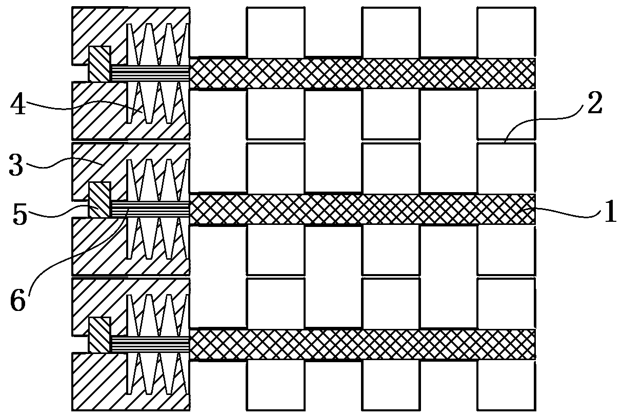
[0019] see figure 1 Each bipolar plate 2 is formed by stacking the cathode plate and the anode plate of the fuel cell, and the cathode plate is on the anode plate. Both sides of the bipolar plate 2 are provided with positioning holes.
[0020] The process of forming the plastic-coated structure 3 and the sealing structure 4 on the bipolar plate 2 is as follows: put the bipolar plate 2 into the injection mold, and the positioning holes on the bipolar plate 2 cooperate with the positioning pins on the injection mold to realize alignment of the bipolar plate 2. The positioning of the pole plate 2, the sealing cavity of the injection mold covers the edge of the bipolar plate 2, injects the hot melt material into the injection mold until it fills the mold cavity, then cools and solidifies, takes out the mold, and the injection molding material is placed on the bipolar plate 2 The overmolding structure 3 and the sealing structure 4 are formed by the last injection molding, and the ...
Embodiment 2
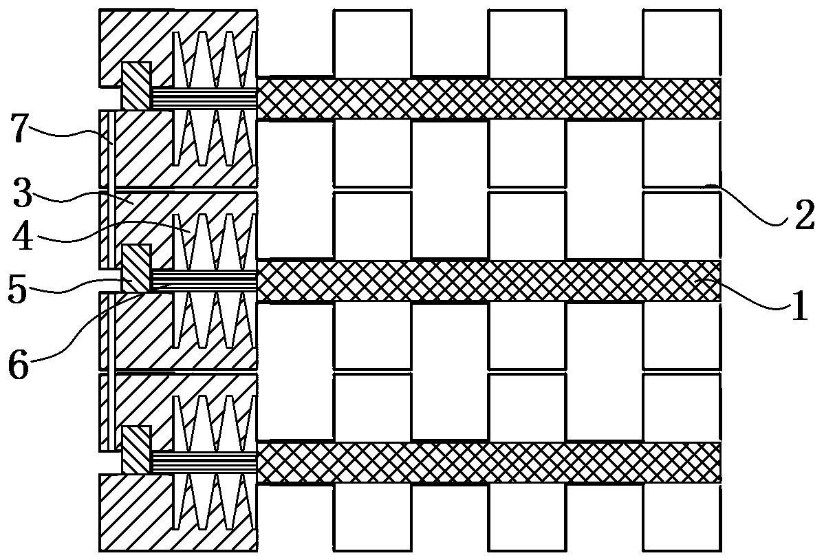
[0024] see figure 2 Each bipolar plate 2 is formed by stacking the cathode plate and the anode plate of the fuel cell, and the cathode plate is on the anode plate. Both sides of the bipolar plate 2 are provided with positioning holes, and the bipolar plate 2 is also provided with a communication hole 7 passing through the cathode side and the anode side.
[0025] The process of forming the plastic-coated structure 3 and the sealing structure 4 on the bipolar plate 2 is as follows: put the bipolar plate 2 into the injection mold, and the positioning holes on the bipolar plate 2 cooperate with the positioning pins on the injection mold to realize alignment of the bipolar plate 2. The positioning of the pole plate 2, the sealing cavity of the injection mold covers the edge of the bipolar plate 2, injects the hot melt material into the injection mold until it fills the mold cavity, then cools and solidifies, takes out the mold, and the injection molding material is placed on the ...
Embodiment 3
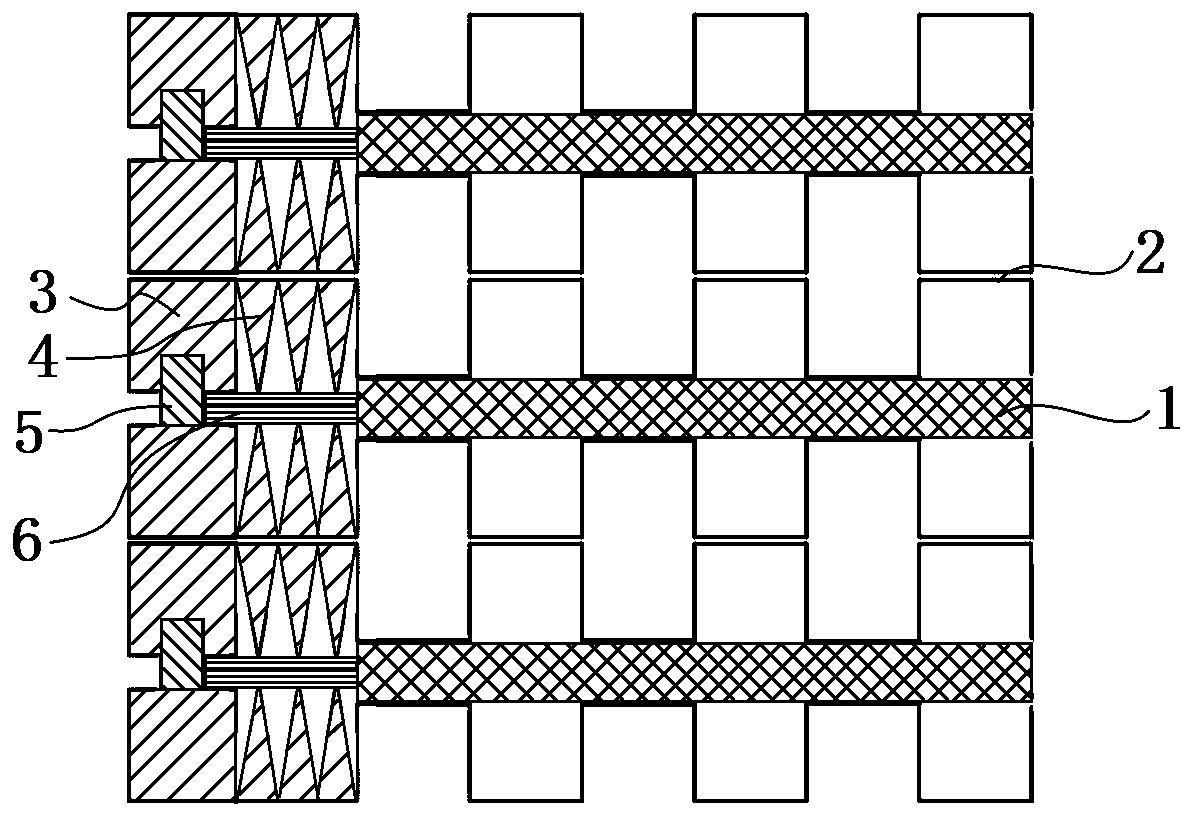
[0029] see image 3 Each bipolar plate 2 is formed by stacking the cathode plate and the anode plate of the fuel cell, and the cathode plate is on the anode plate. Both sides of the bipolar plate 2 are provided with positioning holes.
[0030]The process of forming the plastic-coated structure 3 and the sealing structure 4 on the bipolar plate 2 is as follows: put the bipolar plate 2 into the injection mold, and the positioning holes on the bipolar plate 2 cooperate with the positioning pins on the injection mold to realize alignment of the bipolar plate 2. The positioning of the polar plate 2, the sealed cavity of the injection mold covers the edge of the bipolar plate 2, injects the hot melt material into the injection mold until it fills the cavity, then cools and solidifies, takes out the mold, and injection molds the overmolded structure 3 The edge of the bipolar plate 2 is overmolded with the material to form the overmolded structure 3 . In the above two embodiments, t...
PUM
 Abstract
Description
Claims
Application Information
 - R&D Engineer
- R&D Manager
- IP Professional
- Industry Leading Data Capabilities
- Powerful AI technology
- Patent DNA Extraction
Browse by: Latest US Patents, China's latest patents, Technical Efficacy Thesaurus, Application Domain, Technology Topic.
© 2024 PatSnap. All rights reserved.Legal|Privacy policy|Modern Slavery Act Transparency Statement|Sitemap