
Stator block, stator and motor

A stator and coil technology, applied in the direction of electrical components, electromechanical devices, electric components, etc., can solve problems such as poor control accuracy, low motor power density, and poor insulation of stator windings

Inactive Publication Date: 2018-09-28
GUANDONG MEDIA INTELLIGENT TECH CO LTD
View PDF5 Cites 1 Cited by
  • Summary
  • Abstract
  • Description
  • Claims
  • Application Information

AI Technical Summary

Problems solved by technology

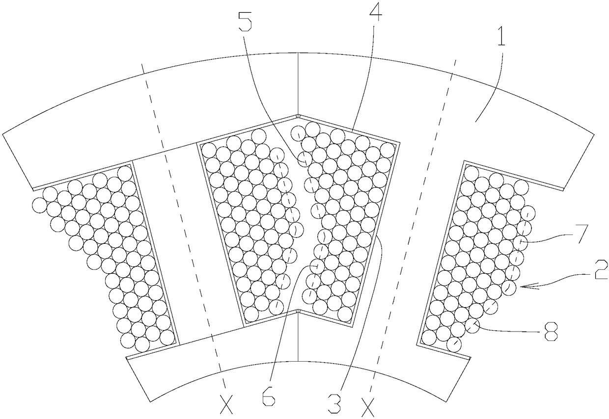
[0003] In practice, the slot fullness of the winding of the stator block is limited by the winding machine, the winding sequence and the wire diameter. Usually, in order to facilitate the winding of the winding machine, the winding parts on both sides of the winding slot are generally along the slot The center line is arranged symmetrically, and the winding machine winds the wires layer by layer to avoid jumping wires, which leaves a lot of space in the winding groove. In this way, when a plurality of such stator blocks are connected to form a stator, such a Due to the low slot full rate of the stator, it will lead to low power density of the motor, severe heat generation, and excessive volume.
[0004] However, if you forcibly use the remaining space to wind the wires on this basis, it is impossible to avoid the wire jumping of the winding machine, and the wires of the winding machine will have problems such as poor insulation of the stator winding, uneven winding, inconsistent coil resistance and inductance, etc., which will eventually lead to The motor torque ripple is too large, the control accuracy is too poor, etc.

Method used


Image

  • Stator block, stator and motor
  • Stator block, stator and motor

Examples


Embodiment Construction

[0025] Specific embodiments of the present invention will be described in detail below in conjunction with the accompanying drawings. It should be understood that the specific embodiments described here are only used to illustrate and explain the present invention, and are not intended to limit the present invention.

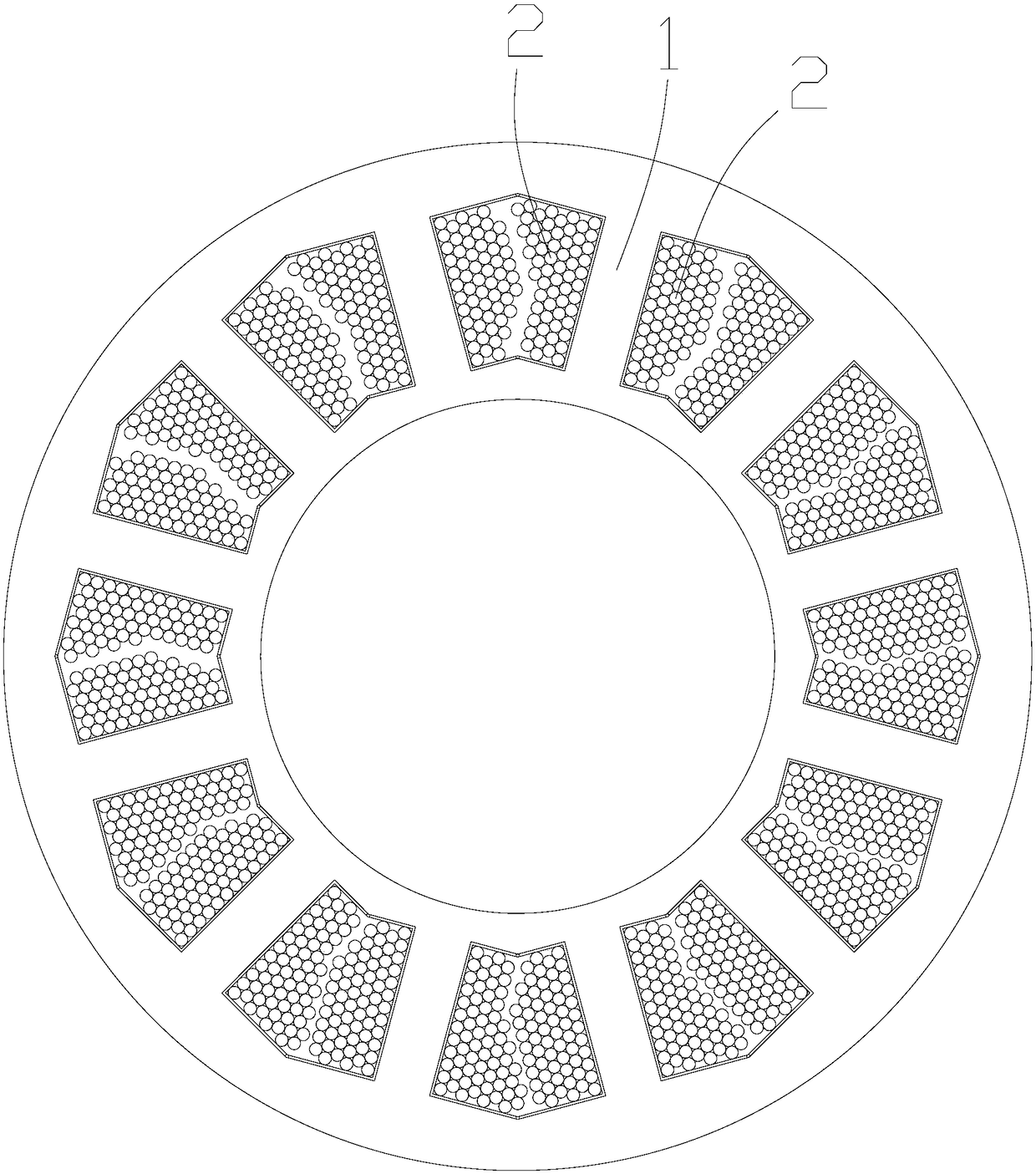
[0026] refer to figure 1 with figure 2 As shown in the structure, the stator block provided by the present invention includes a block core 1 and a coil 2, wherein, the block core 1 is formed with a winding slot 3, and an insulating layer 4 is arranged on the inner surface of the winding slot 3, and the insulating layer 4 In any appropriate way such as ferrule or coating or bonding on the inner surface of the winding groove 3, the coil 2 is wound in the winding groove 3 in sequence along the radial direction of the block core 1 and wound from the inside to the outside multiple layers to form a coil winding, in the circumferential direction of the stator block,...


PUM


Abstract

The invention relates to the technical field of motors, and discloses a stator block, a stator and a motor. The stator block comprises a splicing block core and a coil, wherein the coil forms a coil winding; the first side winding structure of the coil winding and the second side winding structure of the coil winding are asymmetrically arranged relative to the radial center line X of the splicingblock core; and in the first side winding structure, a first side inclined edge is formed on the connecting line of the radially innermost one turn coil of the other multilayer coil outside the firstpreset layer coil, and the part of the first preset layer coil is not shielded to form a first side straight edge; in the second side winding structure, the outermost coil forms a second side straightedge, the connecting line of the second preset layer coil and the radially innermost one turn coil of the outer other multilayer coil forms a second side inclined edge, the shape is complementary after the two stator blocks forming the stator, avoiding excessive residual space in the tolerance line space between the stator blocks, obviously improving the groove fullness rate of the stator, and further improving the power density of the motor and reducing the volume and the cost of the motor.

Description

technical field [0001] The invention relates to the technical field of motors, in particular to a stator block, a stator and a motor. Background technique [0002] At present, the stator includes a stator core and a stator winding wound on the stator core, and the stator winding is basically formed by winding a winding wire on the stator core by a winding machine. In order to facilitate the winding of the winding machine, the stator is divided into multiple stator blocks, so that the winding machine can wind the wires in the winding slots on each stator block, and then connect the stator blocks circumferentially to Form a monolithic stator. [0003] In practice, the slot fullness of the winding of the stator block is limited by the winding machine, the winding sequence and the wire diameter. Usually, in order to facilitate the winding of the winding machine, the winding parts on both sides of the winding slot are generally along the slot The center line is arranged symmetr...

Claims


Application Information

Patent Timeline
IPC IPC(8): H02K3/12H02K3/34
CPCH02K3/12H02K3/345
Inventor 杨国威丁伟兵蒋飞黎思远
Owner GUANDONG MEDIA INTELLIGENT TECH CO LTD
Learn More