Power supply charging control circuit and power supply charging control method

A charging control method and charging control technology, which are applied to electrical components, output power conversion devices, etc., can solve the problem that the compressor operation frequency is slow, the cooling or heating capacity of the air conditioner cannot be output quickly, and the user's comfort experience is affected. and other problems, to achieve the effect of speeding up the charging speed, improving the working stability, and suppressing the surge.

Active Publication Date: 2018-09-28
广东希塔变频技术有限公司
View PDF5 Cites 11 Cited by
  • Summary
  • Abstract
  • Description
  • Claims
  • Application Information

AI Technical Summary

Problems solved by technology

[0004] The main purpose of the present invention is to provide a power supply charging control circuit, the purpose is to solve the problem that when the existing inverter air conditioner is started, the operating frequency of the compressor is relatively slow, which leads to the inability to quickly output the cooling or heating capacity of the air conditioner, thus affecting the user. comfort experience

Method used


Image

  • Power supply charging control circuit and power supply charging control method
  • Power supply charging control circuit and power supply charging control method
  • Power supply charging control circuit and power supply charging control method

Examples


Embodiment Construction

[0034] Embodiments of the present invention are described in detail below, examples of which are shown in the drawings, wherein the same or similar reference numerals designate the same or similar elements or elements having the same or similar functions throughout. The embodiments described below by referring to the figures are exemplary and are intended to explain the present invention and should not be construed as limiting the present invention.

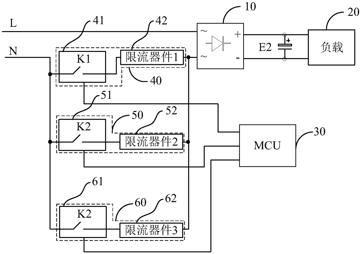
[0035] The present invention proposes a power supply charging control circuit. The control circuit converts AC power into DC high-voltage power. For example, for an AC power input of 220V, the output DC power can reach more than 300V to supply power for loads requiring large currents, such as To supply power to an IPM (Intelligent Power Module) that drives a compressor, or to supply power to an IPM module that drives a DC motor, etc., the basic circuit structure diagram of the power charging control circuit of this embodiment is a...


PUM


Abstract

The invention provides a power supply charging control circuit and a power supply charging control method. The power supply charging control circuit is characterized in that an AC (Alternating Current) power supply outputs a direct current through a rectification module to charge an electrolytic capacitor, so as to form a charging loop, a plurality of current limiting modules are connected in parallel and then connected to the charging loop in series, when the power supply charging control circuit is powered up, one or several current limiting modules in the plurality of current limiting modules are controlled to be conducted at different time by an MCU (Microprogrammed Control Unit), so as to charge the electrolytic capacitor. Through adoption of the power supply charging control circuitof the invention, one or several current limiting modules in the plurality of current limiting modules are controlled to be conducted at different time, so that resistances of current limiting resistors in the charging loop are different when charging is performed at different time, in addition, the resistance of the current limiting resistor which is charged firstly is large so as to suppress surge, and the resistance of the current limiting resistor which is charged later is small so as to accelerate a charging speed, in comparison with a conventional charging circuit with a single current limiting resistor or without current limiting resistor, the power supply charging control circuit of the invention accelerates the charging speed while suppressing a large surge charging current, thereby improving operation stability of the whole circuit device.

Description

technical field [0001] The invention relates to the field of AC / DC power converters, in particular to a power charging control circuit and a power charging control method. Background technique [0002] Currently used in high-power AC / DC (alternating current / direct current) power converters, such as DC high-voltage power supply (over 300V) power converters for compressor drive circuits of inverter air conditioners, large power converters are used on the DC side. High-capacity electrolytic capacitors (more than 400uF) are used for smoothing and filtering. At the moment of power-on, the AC power supply can charge the electrolytic capacitors through current-limiting devices such as PTC or resistors. At present, only a single current-limiting device is used, which requires a long charging time, so As a result, it takes a relatively long time for the power converter to output stable DC power to supply power to subsequent loads; and if the current limiting device is not used, when ...

Claims


Application Information

Patent Timeline
Patent Type & Authority Applications(China)
IPC IPC(8): H02M1/36H02M1/32
CPCH02M1/32H02M1/36
Inventor 王甫敬
Owner 广东希塔变频技术有限公司
Why Eureka
Try Eureka