Tibia distraction, traction, reduction and supporting system
A traction reset and support system technology, applied in the field of medical devices, can solve the problems of inability to use the traction frame, time-consuming and labor-intensive, etc., and achieve the effect of saving operation time, saving resources, and shortening the installation completion time.
- Summary
- Abstract
- Description
- Claims
- Application Information
AI Technical Summary
Problems solved by technology
Method used
Image

Examples
Embodiment Construction
[0018] Embodiments of the technical solutions of the present invention will be described in detail below in conjunction with the accompanying drawings. The following examples are only used to illustrate the technical solutions of the present invention more clearly, and therefore are only examples, rather than limiting the protection scope of the present invention.
[0019] [t4]
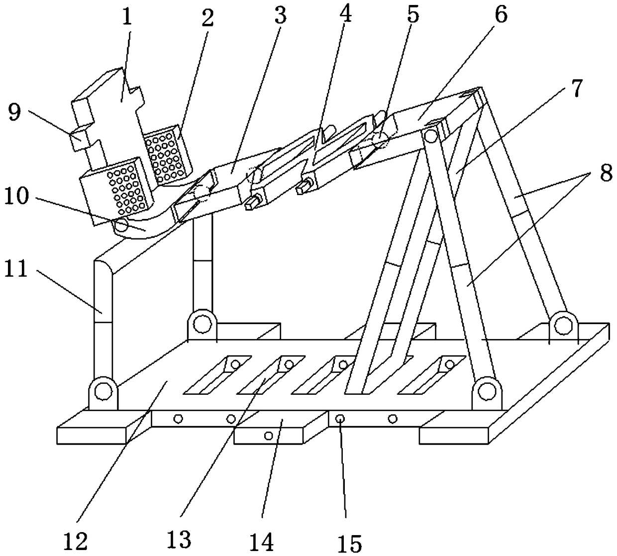
[0020] figure 1 It is a schematic diagram of the structure of the present invention, as shown in the figure: a tibial distraction reduction support system of this embodiment includes a base and a tibial distraction device installed on the base; the tibial distraction device includes a tibial distraction part and Installed on the foot positioning part of the front end of the tibial expansion part; the tibial expansion part includes a front support plate 3, a spreader 4 and a rear support plate 6 connected in sequence from front to back, and the spreader 4 is connected to the front Both the support pl...
PUM
 Abstract
Description
Claims
Application Information