
Airplane movable airfoil face adjustable device based on piezoelectric driving

A piezoelectric drive and adjustment device technology, applied in wing adjustment and other directions, can solve the problems of complex structure, low servo motor power, low specific power, etc., and achieve the effects of high displacement resolution, fast response speed, and large output force

Inactive Publication Date: 2018-10-02
GUANGDONG UNIV OF TECH
View PDF11 Cites 4 Cited by
  • Summary
  • Abstract
  • Description
  • Claims
  • Application Information

AI Technical Summary

Problems solved by technology

[0003] The existing adjustment device of the aircraft adopts a servo motor to control the rotation of the adjusting piece, the rod mechanism connected with the adjusting piece follows the movement of the adjusting piece, and the elevator connected with the rod mechanism follows the movement of the rod mechanism. The motor controls the elevator to control the flight attitude of the aircraft. The servo motor includes motors, circuit boards, gearboxes and other components, which are heavy and complex in structure. Therefore, it is difficult to realize the distributed assembly of movable wings on the same main wing surface when it is applied to small aircraft. Surface and discrete control, and it is difficult to control accurately through the active airfoil control
On the other hand, the power of the servo motor is small, the specific power is small, the response time is long, and the self-locking performance is poor.

Method used


Image

  • Airplane movable airfoil face adjustable device based on piezoelectric driving
  • Airplane movable airfoil face adjustable device based on piezoelectric driving
  • Airplane movable airfoil face adjustable device based on piezoelectric driving

Examples


Embodiment Construction

[0024] In order to make the object, technical solution and advantages of the present invention clearer, the present invention will be further described in detail below in conjunction with the accompanying drawings. It is only stated here that the words for directions such as up, down, left, right, front, back, inside, and outside that appear or will appear in the text of the present invention are only based on the accompanying drawings of the present invention, and are not specific to the present invention. limited.

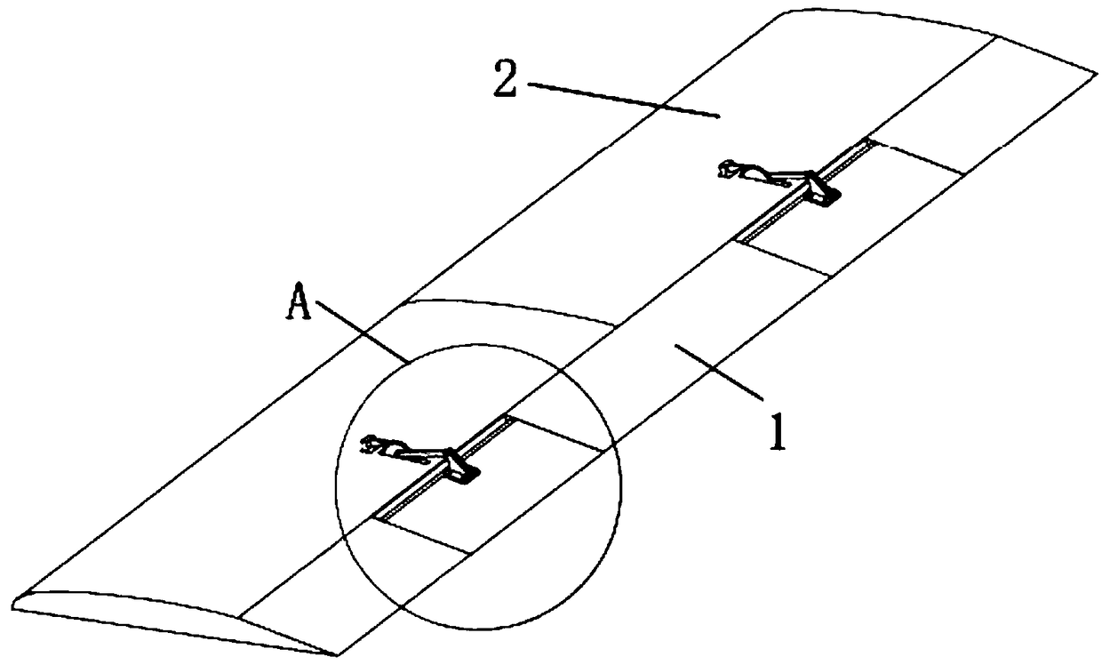
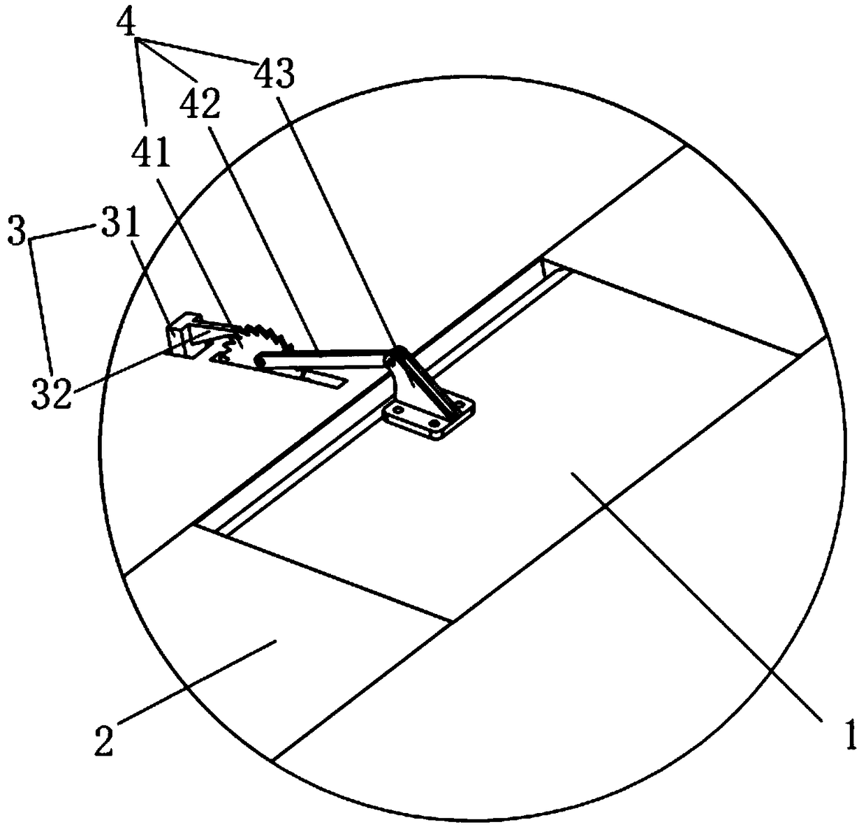
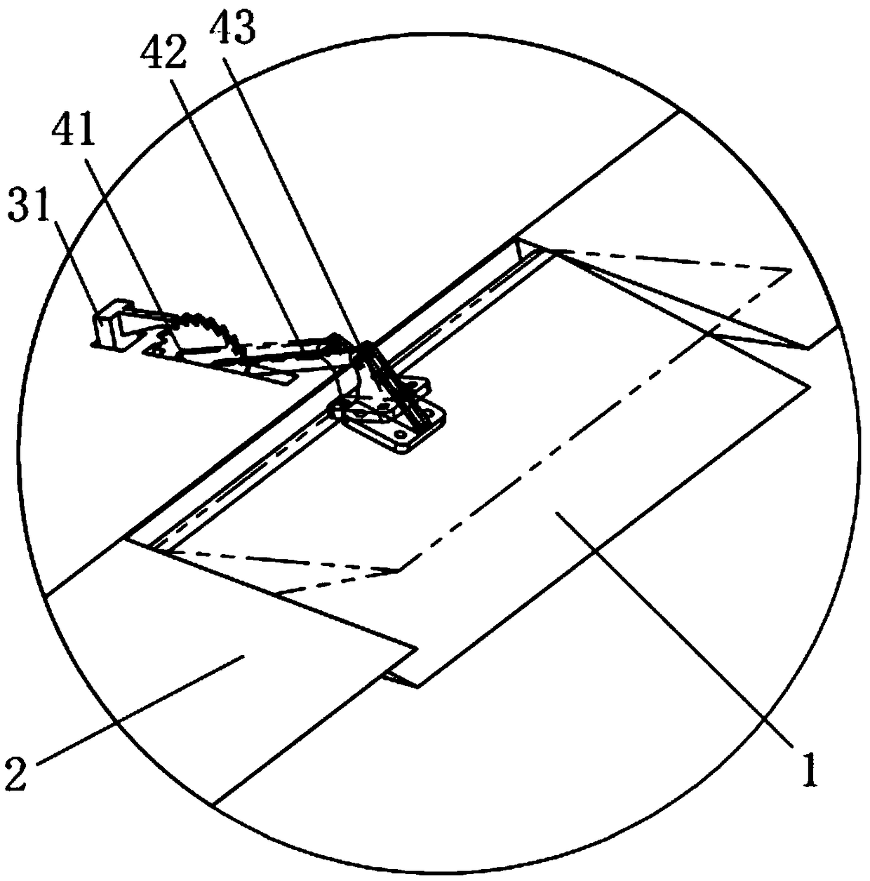
[0025] Such as Figure 1-3 As shown, the embodiment of the present invention provides an aircraft movable wing surface adjustment device based on piezoelectric drive, including a wing 2 composed of at least one movable wing surface 1, a piezoelectric driver 3 connected to the movable wing surface 1, A connecting mechanism 4 connecting the piezoelectric driver 3 and the movable airfoil 1 and a controller electrically connected to the piezoelectric driver 3;

[0...


PUM


Abstract

The invention discloses an airplane movable airfoil face adjustable device based on piezoelectric driving. The airplane movable airfoil face adjustable device includes an airfoil formed by at least one movable airfoil face, a piezoelectric driving machine connected with the movable airfoil face, a connecting mechanism connecting the piezoelectric driving machine and the movable airfoil face and acontroller; the piezoelectric driving machine includes a piezoelectric driving machine body and a driving pawl connected with the piezoelectric driving machine body; the controller is connected with the piezoelectric driving machine and an input electrical signal is transferred to the body, the body is displaced and the pawl displaces with the piezoelectric driving machine body and pushes the connecting mechanism; and under the action of the connecting mechanism the movable airfoil face rotates and angle adjustment of the movable airfoil face is achieved. According to the airplane movable airfoil face adjustable device based on the piezoelectric driving, through the simple movable airfoil face, the piezoelectric driving machine and the connecting mechanism, accurate controlling of the flight attitude of the air plane can be achieved, and the flight requirement of the diminutive airplane in the complex environment and narrow areas is met.

Description

technical field [0001] The invention relates to the technical field of small aircraft wing surface adjustment equipment, in particular to an aircraft movable wing surface adjustment device based on piezoelectric drive. Background technique [0002] At present, small unmanned aircraft are often used in complex flight environments, and the design and optimization of aircraft structures to adapt to changing flight environments is a research hotspot in related fields at this stage. When the wing shape or attitude changes, the attitude of the aircraft is determined by the aerodynamic lift characteristics and drag changes, so the artificial adjustment or adaptation of the wing shape or attitude can change the aerodynamic layout of the aircraft according to the external flying environment, so as to achieve the optimal flight To achieve the best flight status, the wings of the aircraft need to be adjusted. [0003] The existing adjustment device of the aircraft adopts a servo motor...

Claims


Application Information

Patent Timeline
IPC IPC(8): B64C3/38
CPCB64C3/38
Inventor 陈桪何超陈章俊
Owner GUANGDONG UNIV OF TECH
Learn More