Energy saving apparatus for flocculation of industrial waste liquid

A technology of industrial waste liquid and energy-saving devices, applied in the direction of flocculation/sedimentation water/sewage treatment, water/sewage treatment, water/sludge/sewage treatment, etc., can solve the problem of high energy consumption, achieve energy saving and good flocculation effect , the effect of prolonging the mixing time

Inactive Publication Date: 2018-10-02
四川省宏茂环保技术服务有限公司
View PDF0 Cites 3 Cited by
  • Summary
  • Abstract
  • Description
  • Claims
  • Application Information

AI Technical Summary

Problems solved by technology

[0003] The technical problem to be solved by the present invention is: the existing flocculation mixing requires stirring and high energy consumption. The present invention provides an energy-saving device for flocculation of industrial waste liquid which solves the above problems

Method used


Image

  • Energy saving apparatus for flocculation of industrial waste liquid
  • Energy saving apparatus for flocculation of industrial waste liquid

Examples


Embodiment 1

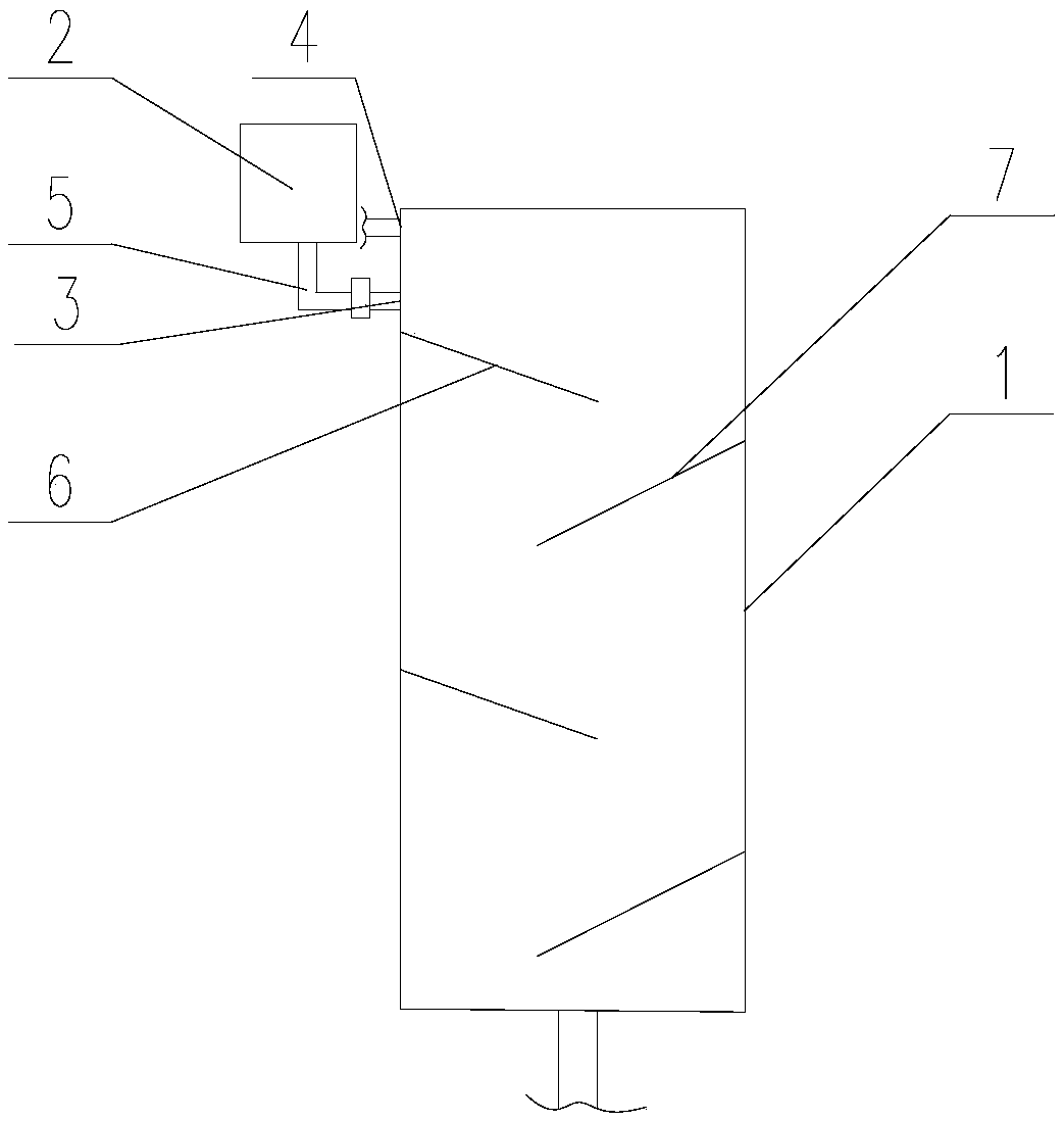
[0020] Such as figure 1 and figure 2 As shown, an energy-saving device for flocculation of industrial waste liquid includes a flocculant high-level tank 2, a central delivery pipe 1, a flocculant addition port 3 and a waste liquid addition port 4, and the lower end of the flocculant high-level tank 2 is connected with a flocculant addition pipe 5. The outlet end of the flocculant addition pipe 5 is connected to the flocculant addition port 3 through a flange, the flocculant addition port 3 and the waste liquid addition port 4 are arranged at the upper end of the central addition pipe, and the waste liquid addition port 4 Located above the flocculant addition port 3, the inner wall of the central conveying pipe 1 is provided with a plurality of first baffles 6 and a plurality of second baffles 7 that are inclined downward and form an excellent arc. The first baffles 6 and The arc surface end of the second baffle plate 7 is in full contact with and fixed to the inner wall of t...

Embodiment 2

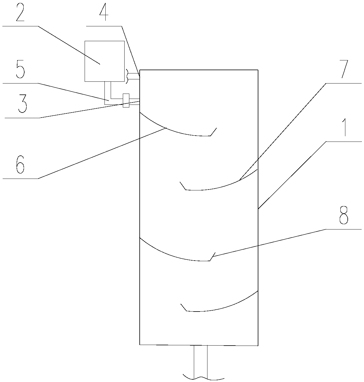
[0023] Such as figure 1 and figure 2 As shown, the difference between this embodiment and Embodiment 1 is that the first baffle plate 6 and the second baffle plate 7 are bent into curved surfaces with their recesses facing upward. In this way, the mixing contact time between the mixing liquid and the baffle is guaranteed to be longer and the mixing is more thorough.

[0024] The free ends of the first baffle plate 6 and the second baffle plate 7 are provided with an upwardly tilted baffle plate 8, which can slow down the flow velocity of the mixed liquid reaching the baffle plate downward, and the liquid that continues to flow on it This part of the mixed liquid will generate momentum and play the role of mixing. When the liquid in this baffle flows to the next baffle, it will accelerate due to the action of gravity, and the flow rate will increase. This can not only prolong the mixing time, but also can Get a steady stream of momentum, making the mixing effect similar to s...


PUM


Abstract

The invention discloses an energy saving apparatus for flocculation of industrial waste liquid and solves the problems that flocculation in the prior art needs stirring and is high in energy consumption. The apparatus includes a flocculant header tank, a central transporting pipe, a flocculant adding inlet, and a waste liquid adding inlet. A flocculant adding pipe is connected to the lower end ofthe flocculant header tank. The flocculant adding inlet and the waste liquid adding inlet are disposed on the upper end of the central transporting pipe, wherein the waste liquid adding inlet is located above the flocculant adding inlet. A plurality of first baffles and a plurality of second baffles, which are inclined down and are in the shape of major arc, are arranged on the inner wall of the central transporting pipe, wherein the arc-shaped ends of the first baffles and second baffles are completely contacted with and fixed to the inner wall of the central transporting pipe. The first baffles are distributed in one side of the central transporting pipe vertically while the second baffles are distributed in the opposite side of the central transporting pipe vertically and are staggeredwith the first baffles. The apparatus can prolong mixing time of the flocculant and to-be-treated industrial waste liquid, so that the liquids are mixed more completely. The apparatus has high mixingefficiency and can save energy.

Description

technical field [0001] The invention relates to the field of industrial waste liquid treatment, in particular to an energy-saving device for flocculation of industrial waste liquid. Background technique [0002] In the production of industrial enterprises, a large amount of waste liquid containing suspended solids is often produced. To deal with these waste liquids, solid-liquid separation is generally required, and the natural settlement of suspended waste liquid cannot be realized or takes a long time because of the relatively fine solid particles. Therefore, there is a method of using flocculants to flocculate and agglomerate fine particles into large particles, which is conducive to sedimentation. In order to allow fine particles to better mix with flocculants, a stirring device is generally used in the flocculation tank. , but this increases the equipment and consumes electricity. Therefore, a spiral tube conveying pipe has appeared to prolong the mixing time of the flo...

Claims


Application Information

Patent Timeline
Patent Type & Authority Applications(China)
IPC IPC(8): C02F1/52
CPCC02F1/5281
Inventor 李列张小玲彭丽琴
Owner 四川省宏茂环保技术服务有限公司
Why Eureka
Try Eureka