Energy-saving dyeing machine

A dyeing machine and dyeing tank technology, applied in the field of dyeing machines, can solve the problems of increasing the burden and cost of sewage treatment, unfavorable cost control of the dyeing process, etc., and achieve the effects of easy follow-up cleaning, simple structure, and improved use efficiency

Active Publication Date: 2018-10-02
宁夏西部皮草有限公司
View PDF4 Cites 2 Cited by
  • Summary
  • Abstract
  • Description
  • Claims
  • Application Information

AI Technical Summary

Problems solved by technology

[0002] In the dyeing process, the dyeing machine is mainly used to dye fur such as sheepskin. In the existing technology, there is a large amount of waste dyeing liquid discharged by the dyeing machine after the dyeing is completed, which increases the burden and cost of sewage treatment, and is not conducive to the cost of the dyeing process. control

Method used


Image

  • Energy-saving dyeing machine
  • Energy-saving dyeing machine
  • Energy-saving dyeing machine

Examples


Embodiment 1

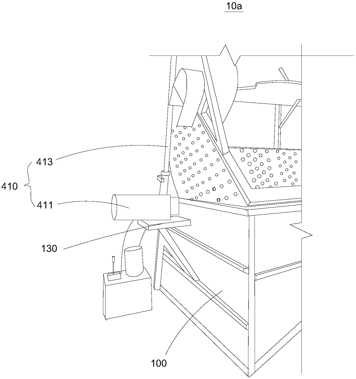
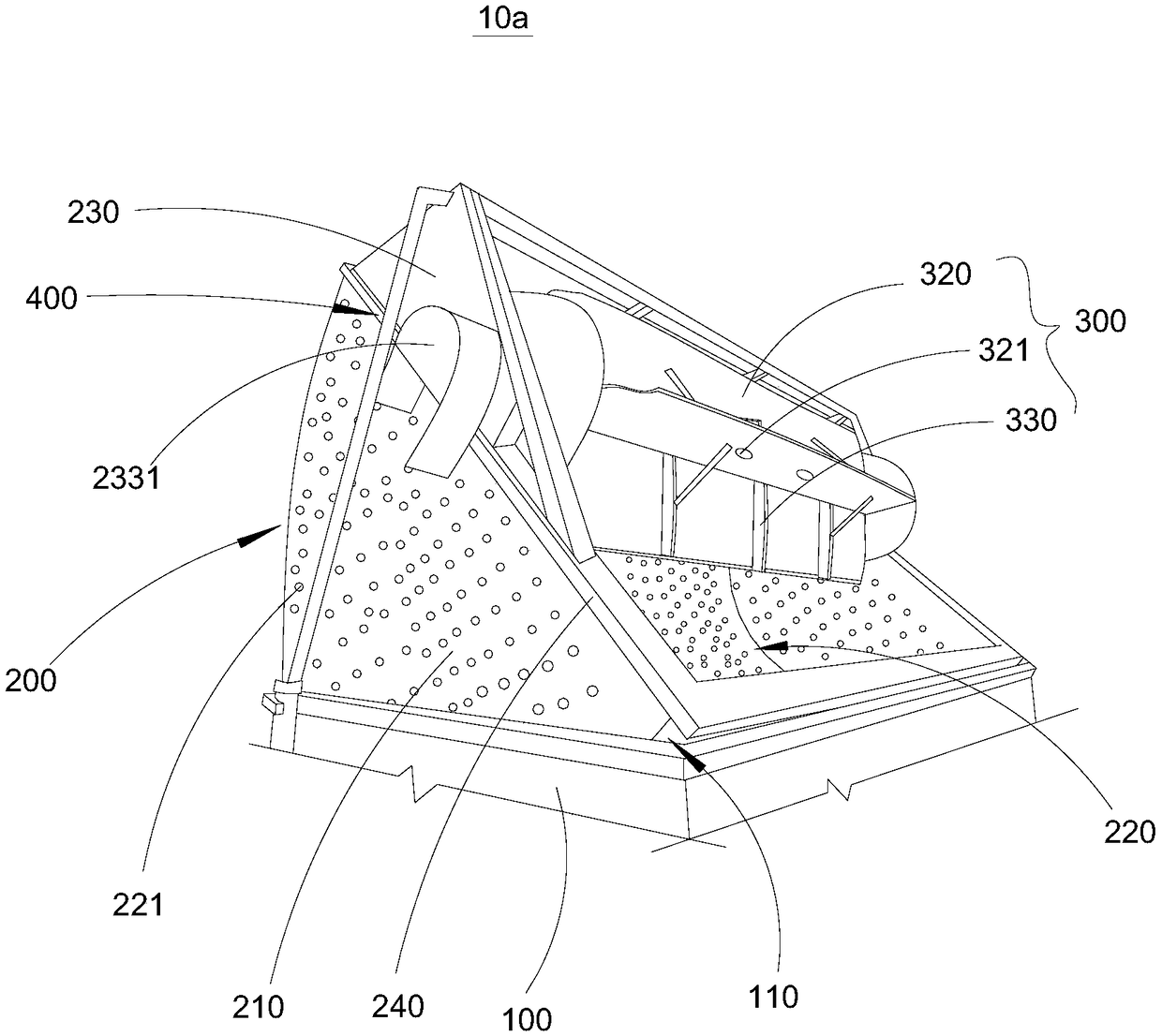
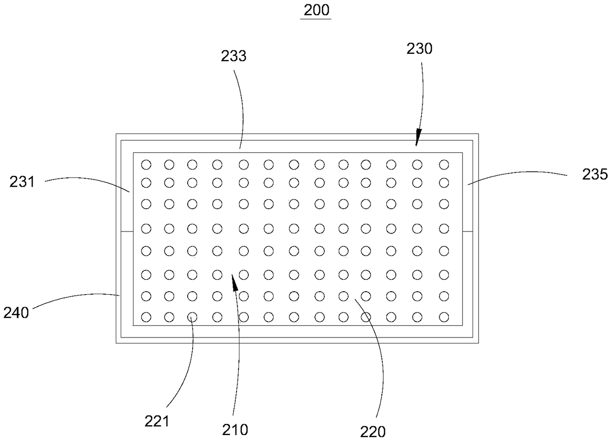
[0023] Please also refer to figure 1 as well as figure 2 , the present embodiment provides an energy-saving dyeing machine 10a, which includes a dyeing machine main body 100, a filter mechanism 200, a stirring mechanism 300, and a power mechanism 400.

[0024] Wherein, the main body 100 of the dyeing machine is provided with a first dyeing tank 110, which is used to hold the dye solution, and then dye sheepskin, rabbit skin or other furs or textiles. Wherein, the longitudinal section of the first dyeing tank 110 can be trapezoidal, rectangular, hemispherical, etc. In this embodiment, the longitudinal section of the first dyeing tank 110 is semicircular, and the projection of the first dyeing tank 110 on the horizontal plane is a rectangle. Facilitate the discharge of the dye solution in the later stage.

[0025] The main body 100 of the dyeing machine is provided with a drain port (not shown), and the first dyeing tank 110 communicates with the drain port for discharging th...

Embodiment 2

[0049] Please refer to Figure 4 This embodiment provides an energy-saving dyeing machine 10b, which is substantially the same as the energy-saving dyeing machine 10a of the first embodiment, the difference between the two is that the energy-saving dyeing machine 10b of this embodiment also includes a water treatment device 500 .

[0050] Specifically, the liquid outlet is connected with a liquid outlet pipe 510 , and the liquid outlet pipe 510 is in communication with the water treatment device 500 .

[0051] Wherein, the water treatment device 500 includes a reclaimed water outlet (not shown in the figure), and the reclaimed water outlet is selectively communicated with the dyeing tank. The liquid inlet of the one-way valve 530 is located on the side of the one-way valve 530 close to the water treatment device 500, and is used for reusing the recovered gray water, effectively saving water resources.

[0052] The working principle of the energy-saving dyeing machine 10b is: ...


PUM


Abstract

The invention relates to an energy-saving dyeing machine and relates to the field of dyeing machines. The energy-saving dyeing machine comprises a dyeing machine main body, a filtering mechanism, a stirring mechanism and a power mechanism. The dyeing machine main body is provided with a first dyeing groove. The filtering mechanism comprises a mounting part and filtering part connected with the mounting part. The filtering part is detachably arranged in the first dyeing groove and provided with a second dyeing groove. The filtering part is provided with a filer hole penetrating through the filtering part. The stirring mechanism is rotationally arranged on the mounting part and partially extends into the second dyeing groove, and a gap is formed between the stirring mechanism and the seconddyeing groove. The power mechanism comprises a first power mechanism which is used for driving the filtering part and selectively separated from the first dyeing groove, and a second power mechanism for driving the stirring mechanism to rotate. The dyeing effect of the energy-saving dyeing machine is good, meanwhile, dyeing liquor and water can be saved effectively, thus, dyeing liquor can be reused, energy is effectively saved, the production cost is reduced, and the energy-saving dyeing machine is environmentally friendly.

Description

technical field [0001] The invention relates to the field of dyeing machines, in particular to an energy-saving dyeing machine. Background technique [0002] In the dyeing process, the dyeing machine is mainly used to dye fur such as sheepskin. In the existing technology, there is a large amount of waste dyeing liquid discharged by the dyeing machine after the dyeing is completed, which increases the burden and cost of sewage treatment, and is not conducive to the cost of the dyeing process. control. Contents of the invention [0003] The object of the present invention is to provide an energy-saving dyeing machine, which has good dyeing effect and can effectively save dye liquor and water, so that the dye liquor can be reused, effectively saves energy, reduces production costs, and is environmentally friendly at the same time. [0004] Embodiments of the present invention are achieved like this: [0005] An energy-saving dyeing machine, which includes a main body of the...

Claims


Application Information

Patent Timeline
Patent Type & Authority Applications(China)
IPC IPC(8): C14C15/00B01D29/56B01D29/01
CPCB01D29/01B01D29/56C14C15/00
Inventor 马旭王自荣李惠琴
Owner 宁夏西部皮草有限公司
Why Eureka
Try Eureka