
Multimodal synchronous phasor-based power system oscillation tracing method and system

A power system and synchronized phasor technology, applied in the field of power systems, can solve the problems of building multi-mode oscillations, without considering the impact, and difficult to meet the requirements of wide-area traceability of multi-mode oscillations, so as to achieve easy online implementation and simple and easy implementation , the effect of clear physical meaning

Active Publication Date: 2018-10-02
TSINGHUA UNIV
View PDF5 Cites 7 Cited by
  • Summary
  • Abstract
  • Description
  • Claims
  • Application Information

AI Technical Summary

Problems solved by technology

However, the existing fundamental synchrophasor power system dynamic monitoring devices and systems, such as PMU (phasor measurement unit, phasor measurement unit) and WAMS (wide-area measurement system, wide-area measurement system) are difficult to meet the multi-mode oscillation Wide-area traceability requirements due to:
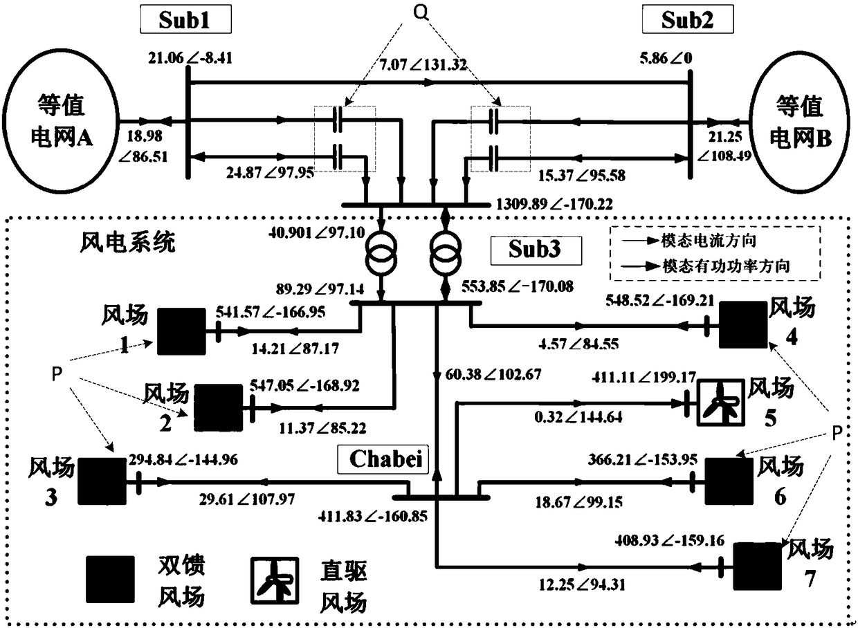
[0004] 1) The fundamental phasor of the existing system is aimed at, without considering the influence of broadband signals from a few Hz to thousands of kHz, and cannot accurately reflect the dynamics of multiple non-power frequency and multiple modes;
[0005] 2) There is no wide-area path for multi-mode oscillation based on phasor information to accurately locate the source and sink of the oscillation

Method used


Image

  • Multimodal synchronous phasor-based power system oscillation tracing method and system
  • Multimodal synchronous phasor-based power system oscillation tracing method and system
  • Multimodal synchronous phasor-based power system oscillation tracing method and system

Examples


Embodiment Construction

[0036] Embodiments of the present invention are described in detail below, examples of which are shown in the drawings, wherein the same or similar reference numerals designate the same or similar elements or elements having the same or similar functions throughout. The embodiments described below by referring to the figures are exemplary and are intended to explain the present invention and should not be construed as limiting the present invention.

[0037]The power system oscillation traceability method and system based on multi-mode synchrophasors proposed according to the embodiments of the present invention will be described below with reference to the accompanying drawings. System oscillation traceability system.

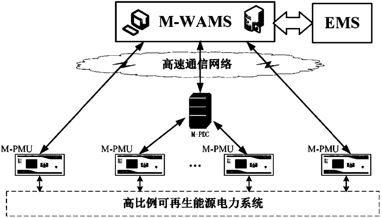
[0038] figure 1 It is a structural schematic diagram of a power system oscillation traceability system based on multi-mode synchrophasors according to an embodiment of the present invention.

[0039] Such as figure 1 As shown, the power system oscillation t...


PUM


Abstract

The invention discloses a multimodal synchronous phasor-based power system oscillation tracing method and system. The system comprises multiple multimodal phasor measurement units, a multimodal phasorconcentrator and a multimodal oscillation wide area monitoring / analysis and tracing platform, wherein the multimodal phasor measurement units are used for extracting all oscillation modes for bus voltage and all phases of current of a line, acquiring corresponding phasors, acquiring positive, negative and zero-sequence phasors in each oscillation mode and corresponding complex power and marking asynchronous time scale to obtain phasor data; the multimodal phasor concentrator is used for communicating with the multiple multimodal phasor measurement units and storing the phasor data; and the multimodal oscillation wide area monitoring / analysis and tracing platform is used for receiving the phasor data transmitted by the multimodal phasor concentrator, carrying out resynchronization on thephasor data according to the time scale, the phasor data are stored in a real-time or historical database to realize multimodal tracing. The system can realize accurate power system multimodal oscillation tracing, the physical meaning is clear, online execution is easy and simple to realize.

Description

technical field [0001] The invention relates to the technical field of power systems, in particular to a method and system for tracing the source of power system oscillation based on multi-mode synchronized phasors. Background technique [0002] In modern power systems, the widespread access of power electronic converters and renewable energy power generation not only changes the form of primary equipment in the power grid, but also significantly changes the power grid with its unique multi-time-scale control mode, low inertia, and wide-band response characteristics. The dynamic behavior of the system brings new stability problems. In recent years, the problem of multi-mode oscillation caused by the large-scale connection of wind power, photovoltaic and other variable current power sources to the power grid has been particularly prominent, which seriously threatens the equipment safety, system stability and power quality of modern power grids, and has become a constraint to ...

Claims


Application Information

Patent Timeline
IPC IPC(8): G01R31/08
CPCG01R31/088G01R19/2513G01R21/133Y02E40/70Y02E60/00Y04S10/22
Inventor 谢小荣
Owner TSINGHUA UNIV
Learn More