Breadboard corresponding to circuit schematic diagram and simple [-shaped breadboard jumper series

A technology of circuit schematics and breadboards, which is applied in the direction of educational appliances, instruments, teaching models, etc., and can solve the problems of inconvenient storage, too many, and inconvenient finding of suitable lengths, etc.

Active Publication Date: 2018-10-02
陈竹
View PDF9 Cites 0 Cited by
  • Summary
  • Abstract
  • Description
  • Claims
  • Application Information

AI Technical Summary

Problems solved by technology

In order to achieve different spans, the U-shaped breadboard jumpers used in conjunction with existing breadboards require too many types of jumpers, which is not easy to store or find a suitable length

Method used


Image

  • Breadboard corresponding to circuit schematic diagram and simple [-shaped breadboard jumper series
  • Breadboard corresponding to circuit schematic diagram and simple [-shaped breadboard jumper series
  • Breadboard corresponding to circuit schematic diagram and simple [-shaped breadboard jumper series

Examples


Embodiment 1

[0069] The structure of Embodiment 1 of the present invention is as follows:

[0070] Embodiment 1 of the present invention selects such as Figure 8 Shown are the existing range of Breadboard Jumpers and Flex Breadboard Jumpers. Such as Figure 9 Shown is the existing series of jumper wires for breadboards with spans that form an arithmetic sequence, and the tolerance is 1 times the standard hole center distance.

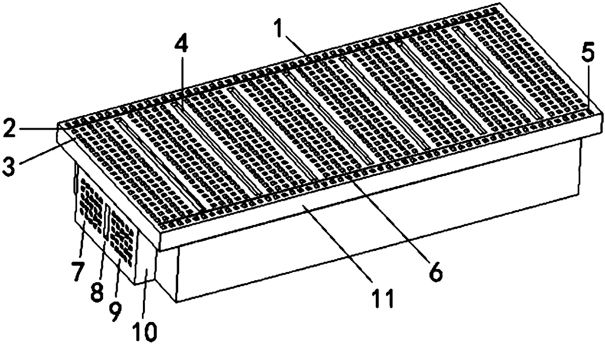
[0071] Depend on Figure 2 to Figure 11 It can be seen that the length of the new breadboard in Example 1 of the present invention is greater than the width, the width direction is longitudinal, and the length direction is horizontal. One side of the new breadboard is provided with a long row of continuous equidistant jacks across the entire length, which is the positive electrode insertion area; The other side of the breadboard is provided with a long row of continuous equidistant jacks across the entire length, which is the negative pole insertion area. The j...

Embodiment 2

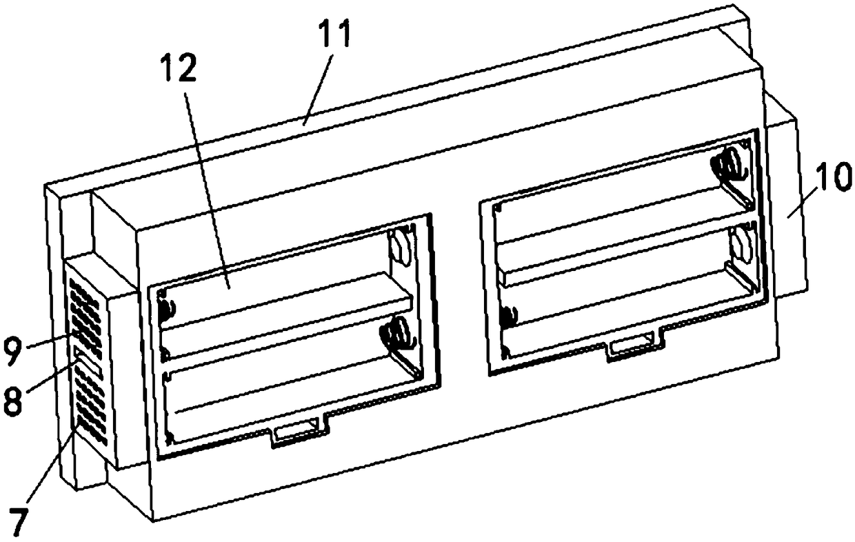
[0073] Embodiment 2 of the present invention such as Figure 12 Shown: The difference from Example 1 is that one side of the new-style breadboard in Example 2 is provided with two long rows of continuous equidistant jacks across the entire length, which are positive plug-in areas; the other side of the new-style breadboard is provided with Two long rows of continuous equidistant jacks are the negative pole plugging area. The component insertion area is divided into 10 independent insertion areas by 9 longitudinal isolation grooves.

Embodiment 3

[0075] The structure of embodiment 3 of the present invention is as follows:

[0076] Embodiment 3 of the present invention includes a novel breadboard and a streamlined series of breadboard jumpers, which can be supplemented with a small amount of soft breadboard jumpers if necessary. Streamlined breadboard jumper series such as Figure 15 As shown, the spans of the eight kinds of breadboard jumpers are 1 times, 3 times, 6 times, 9 times, 12 times, 15 times, 18 times and 21 times of the standard hole center distance of the breadboard (usually 2.54 mm). ,Such as Figure 16 shown.

[0077] Such as Figure 13 to Figure 16 As shown, the length of the new breadboard in Example 3 of the present invention is greater than the width, the width direction is longitudinal, and the length direction is horizontal; one side of the new breadboard is provided with 3 horizontal rows of continuous equidistant jacks across the entire length, which is the positive electrode insertion area ; T...


PUM


Abstract

The invention belongs to the technical field of electronic circuit experiment teaching tools, and particularly relates to a breadboard corresponding to a circuit schematic diagram and a simple [-shaped breadboard jumper series. A positive plug-in area of a split type breadboard has 3 horizontal rows of jacks which are conductive with each other internally; a negative plug-in area has 3 horizontalrows of jacks which are conductive with each other internally; a component plug-in area is a rectangular array composed of 5x20 jacks, conductive clips of five jacks in the same horizontal row are conductive with each other, and jacks in different horizontal rows are insulated from each other. The plurality of split type breadboards are connected by plugging conductive pillars in conductive pillarjacks on the back of positive and negative indicating lines, so that all the positive plug-in areas are conductive with each other, and all the negative plug-in areas are conductive with each other.The simple [-shaped breadboard jumper series spans 1x, 3x, 6x, 9x, 12x, 15x, 18x and 21x the standard hole pitch, moves up and down in the range of the 3 horizontal rows of the jacks of the positive and negative plug-in areas, and can be connected to any position of the component plug-in areas from the positive and negative plug-in areas.

Description

technical field [0001] The invention belongs to the technical field of electronic circuit experiment teaching tools, and in particular relates to a novel breadboard and a streamlined breadboard jumper series capable of splicing and inserting an experimental circuit completely corresponding to the component direction and wire running of the circuit schematic diagram. Background technique [0002] The circuit schematic diagram directly reflects the structure and working principle of the electronic circuit. If the experimental circuit can completely correspond to the circuit schematic diagram in terms of component location and wire routing, it will not only facilitate beginners to get started with electronic circuits from experiments, but also facilitate electronic engineers to design, debug, and analyze electronic circuits. [0003] The use of breadboards in electronic circuit experiments has many advantages, such as electronic components can be inserted or pulled out as neede...

Claims


Application Information

Patent Timeline
Patent Type & Authority Applications(China)
IPC IPC(8): G09B23/18
CPCG09B23/183
Inventor 陈竹郭春芳陈光
Owner 陈竹
Why Eureka
Try Eureka