
A device and method for frequency measurement based on mach-zehnder type optical filter

An optical filter, frequency measurement technology, applied in electromagnetic transmitters, electromagnetic wave transmission systems, electrical components, etc., can solve the problems of lack of actual measurement effect, large measurement error value, low measurement error, etc., to achieve strong practical operability , the effect of large bandwidth and improved frequency measurement response performance

Active Publication Date: 2021-07-23
XIDIAN UNIV
View PDF3 Cites 0 Cited by
  • Summary
  • Abstract
  • Description
  • Claims
  • Application Information

AI Technical Summary

Problems solved by technology

Due to the limitations of experimental conditions, most of the current frequency measurement research is mainly for theoretical derivation and simulation verification, and lacks the test of actual measurement results.
In addition, the measurement error value in the experiment is relatively large, and the measurement range is relatively small
[0005] (2) Many current schemes are mainly single-frequency measurement, which is insufficient in actual combat
[0006] The difficulty and significance of solving the above technical problems: it is of great significance to solve the problems existing in the existing technology and realize the requirements of low measurement error and high sensitivity; and in actual combat, for complex electromagnetic environments, the signals that need to be processed by the receiving end are often multiple The synthesis of frequencies poses a great challenge to many current frequency measurement schemes. In order to adapt to complex frequency measurement environments, today's frequency measurement technologies must be able to adapt to more complex measurement environments

Method used


Image

  • A device and method for frequency measurement based on mach-zehnder type optical filter
  • A device and method for frequency measurement based on mach-zehnder type optical filter
  • A device and method for frequency measurement based on mach-zehnder type optical filter

Examples


Embodiment Construction

[0026] In order to make the object, technical solution and advantages of the present invention more clear, the present invention will be further described in detail below in conjunction with the examples. It should be understood that the specific embodiments described here are only used to explain the present invention, not to limit the present invention.

[0027] Such as figure 1 As shown, the present invention utilizes the schematic diagram of the device for frequency measurement of the Mach-Zehnder type optical filter; wherein the incident microwave signal is modulated by a polarization modulator to generate a modulated signal; the polarization direction of the light wave is adjusted by a polarization controller, and realized by a coupler The light wave signal is divided into two identical sub-signals; combined with the polarizer to realize the function of intensity modulation, through the filter, and finally through the photoelectric detector to realize the photoelectric ...


PUM


Abstract

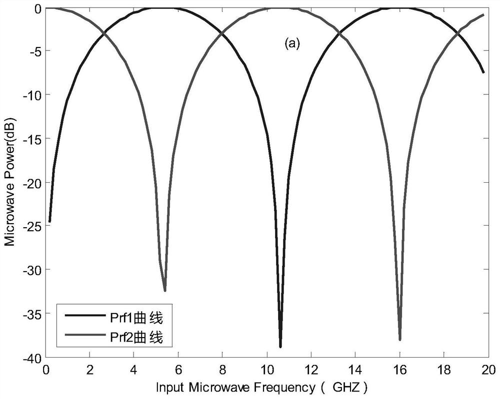
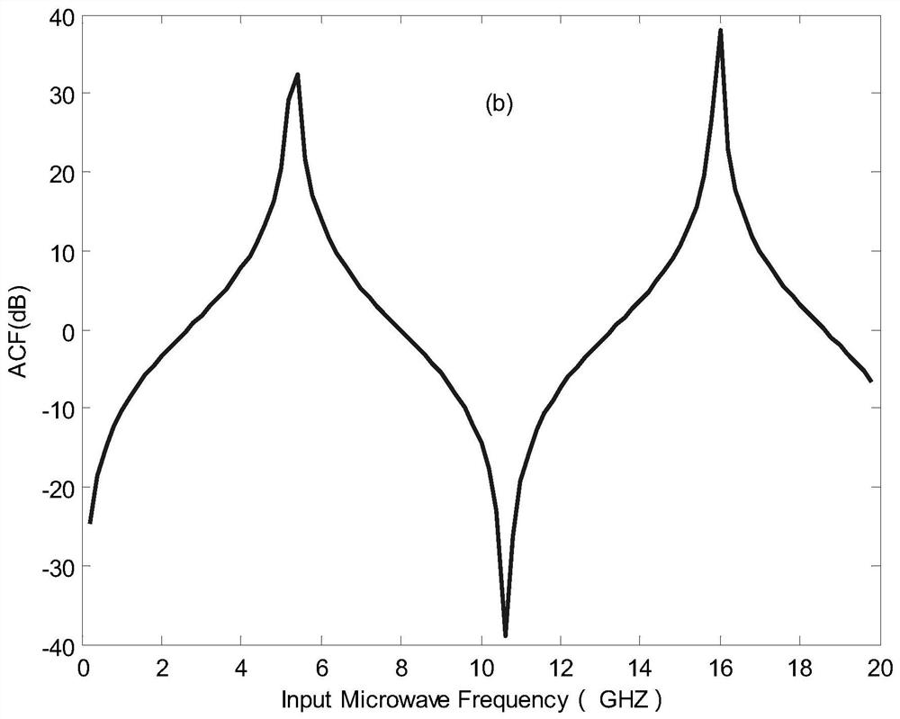
The invention belongs to the technical field of microwave and optical communication, and discloses a device and method for frequency measurement based on a Mach-Zehnder type optical filter, including a laser light source (LD), a polarization modulator (PoLM), a polarization controller (PC), Coupler, polarizer (Pol), optical filter (Filter), erbium-doped fiber amplifier (EDFA) and photodetector (PD). In this scheme, an intensity modulator and a phase modulator can be equivalently formed in the upper and lower channels by using a polarization modulator plus a polarization controller and a polarizer, and the frequency measurement range can be adjusted by adjusting the time delay device of the optical filter. After the modulation signals of the upper and lower channels pass through the optical filter, photoelectric conversion occurs at the photodetector. After signal processing, the amplitude comparison function (ACF) related to the frequency of the signal to be measured can be obtained, and then the frequency measurement function can be realized. This scheme has the characteristics of simple structure, convenient tuning of frequency range and precision, and strong practicability.

Description

technical field [0001] The invention belongs to the technical field of microwave and optical communication, and in particular relates to a device and method for frequency measurement based on a Mach-Zehnder type optical filter. Background technique [0002] At present, the existing technologies commonly used in the industry are as follows: Microwave photonics is an emerging interdisciplinary subject. Its research scope includes photonic generation of microwave signals, microwave photonic signal processing, microwave frequency measurement based on photon technology, and optoelectronic devices working at microwave frequencies. Many functions that are difficult to realize in traditional microwave systems can be realized by using microwave photonic technology. Therefore, microwave photonics technology has received extensive attention in recent years and has been widely used in many fields such as military, medical, communication, and aerospace. With the increase of the signal ...

Claims


Application Information

Patent Timeline
Patent Type & Authority Patents(China)
IPC IPC(8): H04B10/54H04B10/548H04B10/079
CPCH04B10/0795H04B10/54H04B10/548
Inventor 尚磊李刚张恒伟殷惠惠韩兴忠介玺
Owner XIDIAN UNIV
Learn More