Bead stringing structure of full automatic bead stringing machine

A bead stringing machine, fully automatic technology, applied in jewelry, clothing, applications, etc., can solve the problems of inconveniently taking beads, low operation safety, and low production efficiency, and achieve improved bead stringing efficiency, simple threading, and production and processing high efficiency effect

Inactive Publication Date: 2018-10-09
ZHEJIANG BUSINESS TECH INST
View PDF5 Cites 2 Cited by
  • Summary
  • Abstract
  • Description
  • Claims
  • Application Information

AI Technical Summary

Problems solved by technology

[0002] In jewelry processing, it is often necessary to string multiple beads together. The existing method generally uses manual beading. If beads with sharp corners, such as diamond-shaped beads, are encountered, the worker will Not only is it inconvenient to take this kind of beads, but also your fingers are easy to scratch. In the process of beading, you need to pass the lead wire through the through hole on the bead. The material of the lead wire can be nylon, fine steel wire, etc. It is easy to scratch fingers, so the existing beading method not only has low production efficiency, but also the operation safety of workers is not high. Although there has been an arrangement and feeding structure suitable for bead arrangement, that is, the application number is 201610761578.8 Chinese patent application, but there is no matching beaded structure, so the present invention makes improvements on this basis, and needs to develop a beaded structure that can automatically pass the lead wire through the bead

Method used


Image

  • Bead stringing structure of full automatic bead stringing machine
  • Bead stringing structure of full automatic bead stringing machine
  • Bead stringing structure of full automatic bead stringing machine

Examples


Embodiment Construction

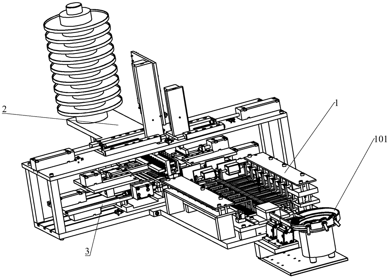
[0029] Such as figure 1 As shown, a fully automatic bead stringing machine includes an arrangement feeding structure 1, a wire feeding structure 2 and a beading structure 3; the arrangement feeding structure 1 includes a vibration queuing and sorting assembly 101, a beading guide assembly, a beading length control assembly, and a beading lateral push assembly , beaded vertical push assembly, next process receiving slot; vibration queuing and sorting assembly 101 includes a vibrating disc host and a delivery slot; the beading guide assembly includes a guide slot; the bead delivery length control assembly includes a length control push electromagnet, a length control connecting rod and a length Control the push slider groove; the beaded horizontal push assembly includes a horizontal push cylinder, and the beaded vertical push assembly includes a longitudinal push cylinder. After a number of scattered beads are arranged in a feeding structure, they are arranged in a row in the rec...


PUM


Abstract

The invention provides a bead stringing structure of a full automatic bead stringing machine. The bead stringing structure comprises a bead stringing bracket, a left cover closing component and a right cover closing component are mutually matched and are arranged on the bead stringing bracket, the left cover closing component comprises a left traction block, a plurality of left cushion blocks, a plurality of left guide blocks and a plurality of left pressing blocks, the right cover closing component comprises a right traction block, a plurality of right cushion blocks, a plurality of right guide blocks and a plurality of right pressing blocks; the left guide blocks and the right guide blocks are respectively located on the upper sides of the left cushion blocks and the right cushion blocks, an arc left leading wire groove and an arc right leading wire groove are respectively arranged in the end faces of the adjacent sides of the left guide block and the right guide block, the left leading wire groove and the right leading wire groove are closed to define a channel which allows a leading wire to go through, a cutting rod is arranged in the left guide block, and a relief hole is arranged in the right guide block. The ordered beads are stringed to be mutually connected together, the stringing is simple and fast, the degree of automation is relatively high, the bead stringing efficiency is greatly improved, and the product quality is improved.

Description

technical field [0001] The invention relates to the technical field of bead stringing mechanical appliances, in particular to a bead stringing structure of a fully automatic bead stringing machine. Background technique [0002] In jewelry processing, it is often necessary to string multiple beads together. The existing method generally uses manual beading. If beads with sharp corners, such as diamond-shaped beads, are encountered, the worker will Not only is it inconvenient to take this kind of beads, but also your fingers are easy to scratch. In the process of beading, you need to pass the lead wire through the through hole on the bead. The material of the lead wire can be nylon, fine steel wire, etc. The lead wire of the fine steel wire is also It is easy to scratch fingers, so the existing beading method not only has low production efficiency, but also has low operational safety for workers. Although there has been an arrangement and feeding structure suitable for rowing ...

Claims


Application Information

Patent Timeline
Patent Type & Authority Applications(China)
IPC IPC(8): A44C27/00
CPCA44C27/00
Inventor 徐生肖国华卞平
Owner ZHEJIANG BUSINESS TECH INST
Why Eureka
Try Eureka