
Implant tools for fixation of orthopedic prostheses

A technology of implantation and tools, which is applied in the field of implantation tools for orthopedic prosthesis fixation, and can solve problems such as small visual space, falling off, and affecting surgical effects

Active Publication Date: 2021-01-01
MICROPORT ORTHOPEDICS SUZHOU CO LTD +1
View PDF7 Cites 0 Cited by
  • Summary
  • Abstract
  • Description
  • Claims
  • Application Information

AI Technical Summary

Problems solved by technology

In particular, when the implant position of the acetabular cup deviates, it is more complicated to determine the position and direction of the screw, especially when performing minimally invasive surgery, the operation of implanting the screw is more difficult due to the small visual space of the operator
[0006] Second, the implantation position and direction of the screw are mainly affected by the line of sight, the position of the patient, the distribution of the reserved holes on the acetabular cup, and the guide line engraved on the acetabular cup, which makes it impossible for the operator to accurately find the center of the screw. , when the screw implantation position is inaccurate, it will lead to the risk of screw loosening or even falling off, which will affect the overall surgical effect

Method used


Image

  • Implant tools for fixation of orthopedic prostheses
  • Implant tools for fixation of orthopedic prostheses
  • Implant tools for fixation of orthopedic prostheses

Examples


Embodiment 1

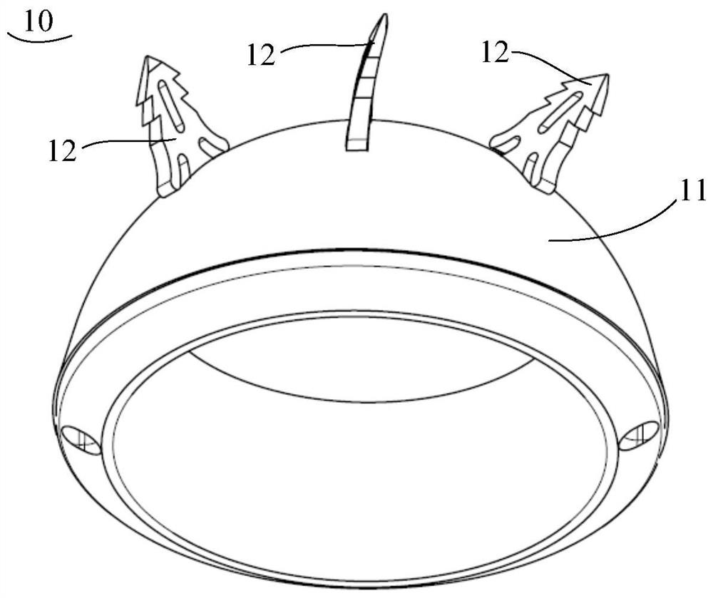
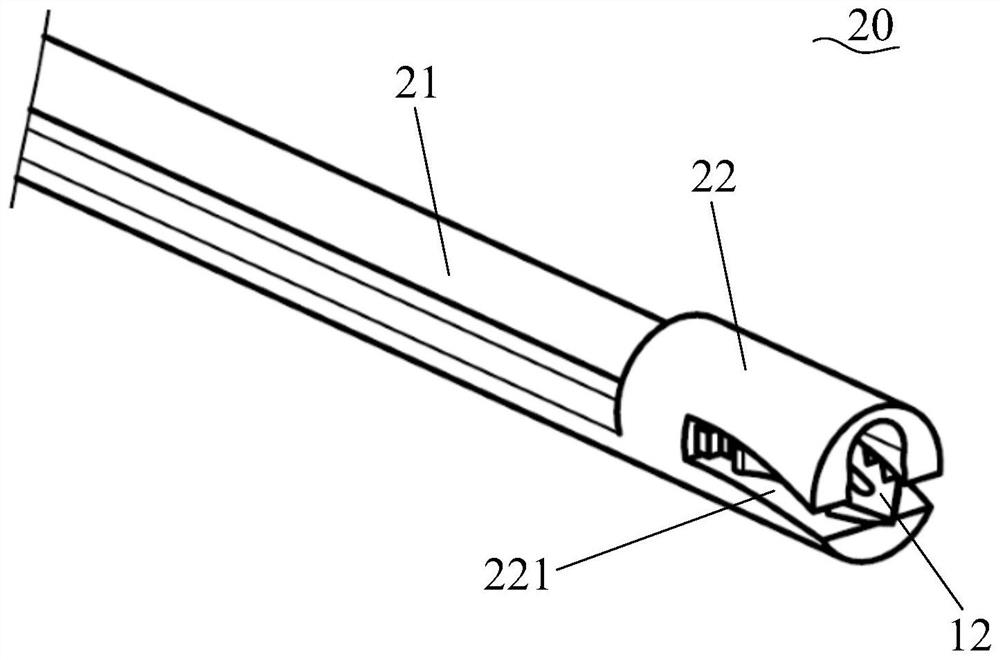
[0056] refer to Figure 2a with Figure 2b , the present embodiment provides an implant tool 20, comprising a push rod 21 and a hollow sleeve 22, the distal end of the sleeve 22 is provided with a slot 221, and one end of the slot 221 is connected to the far end of the sleeve 22. End 22a passes through. The locking groove 221 can be through the entire sleeve 22 in a transverse direction, or can be a cavity wall that only penetrates one side of the inner cavity 222 of the sleeve 22 in a transverse direction, or can be a cavity wall on both sides of the inner cavity 222 of the sleeve 22 None of them are cut through by the draw-in groove 221. When the cavity walls on both sides of the inner cavity 222 are not cut through by the locking groove 221, the locking groove 221 can be set on the cavity wall on one side of the inner cavity 222, or can be set on both sides of the inner cavity 222 at the same time. On the wall of the cavity (that is, the width of the locking groove 221 i...

Embodiment 2

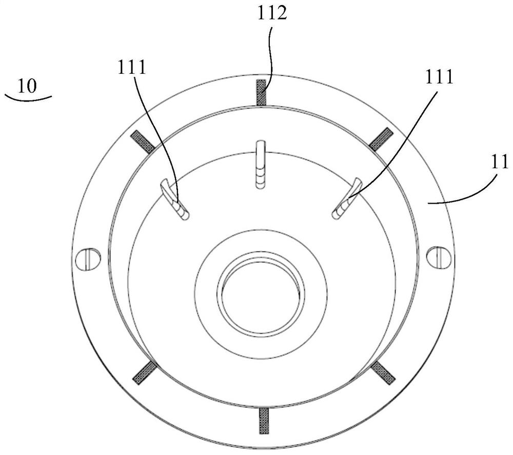
[0069] The acetabular cup provided in this embodiment is basically the same as that in Embodiment 1, and only the differences in the implantation tool will be described below. Wherein, the implantation tool 20 provided in Embodiment 1 can only implant the anchor piece 12 into the predetermined slot 111 along a fixed direction, however, the implantation tool 30 provided in this embodiment can adjust the implantation direction of the anchor piece 12 to Insert into the predetermined slot 111.

[0070] refer to Figure 6a , 6b , 7a and 7b, this embodiment provides an implant tool 30, including a push rod 31, a sleeve 32 and a driving mechanism, and the sleeve 32 includes a first part 32a and a second part 32b with a slot 221, so The first part 32a is disposed on the proximal end of the second part 32b, and the driving mechanism is connected to the second part 32b and used to drive the second part 32b to rotate relative to the first part 32a. In another embodiment, the slot 221 ...


PUM


Abstract

The invention provides an implant tool for orthopedic prosthesis fixation, the implant tool includes a push rod and a sleeve, the distal end of the sleeve is provided with a connecting piece, an implant and the connecting piece In combination, the implant is pushed out of the connecting piece into an orthopedic prosthesis through the push rod in the sleeve. This fixation method does not require drilling holes in the acetabulum and does not require complicated alignment. The operation is relatively simple and the operation time is short. In particular, the sleeve has a relatively rotatable first part and a second part, so that the implant can enter the bone tissue of the human body through the installation position on the acetabular cup prosthesis at an arc angle, which is convenient for implantation and The arc angle facilitates the fixation of the implant.

Description

technical field [0001] The invention relates to the technical field of medical instruments, in particular to an implant tool for orthopedic prosthesis fixation. Background technique [0002] In total hip replacement, after the acetabular cup is implanted, it is necessary to fix the acetabular cup to the acetabulum to ensure that the acetabular cup will not loosen even if it is subjected to a large impact during movement, especially when the bone is not This requirement is especially pronounced with porosity structures that are fully grown into the outer surface of the acetabular cup, or where the coefficient of friction of the outer surface of the acetabular cup is too low. [0003] At present, the acetabular cup is mostly fixed by screwing into a reserved hole on the acetabular cup. To complete this process accurately, it is first necessary to drill screw holes on the acetabulum corresponding to the reserved holes of the acetabular cup, and then use tools to insert screws,...

Claims


Application Information

Patent Timeline
Patent Type & Authority Patents(China)
IPC IPC(8): A61F2/46A61B17/92
CPCA61B17/92A61F2/4603A61F2/4609A61F2002/4635
Inventor 孙延东胡晓苏
Owner MICROPORT ORTHOPEDICS SUZHOU CO LTD
Learn More