Self-driven river sand magnetic separator
A magnetic separator, self-driven technology, applied in magnetic separation, solid separation, chemical instruments and methods, etc., can solve the problems of unfavorable sand field operation, complex transmission mechanism, river ecological damage, etc., to reduce mechanical transmission, volume optimization, The effect of avoiding energy waste
- Summary
- Abstract
- Description
- Claims
- Application Information
AI Technical Summary
Problems solved by technology
Method used
Image
Examples
Embodiment 1
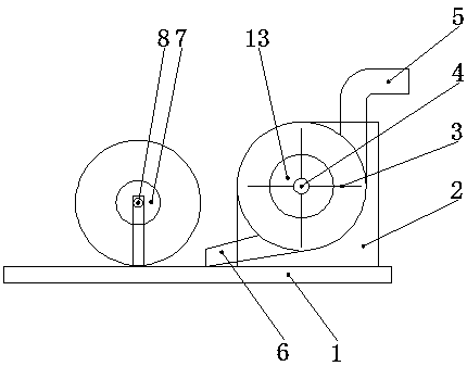
[0030] Such as figure 1 Shown, a kind of self-driven river sand magnetic separator comprises platform 1, the magnetic separation device that is arranged on platform 1 and the turbine device, and described turbine device comprises casing 2, the turbine shaft 4 that is arranged in casing 2, The turbine blade 3 arranged on the turbine shaft 4, the river sand inlet 5 arranged on the upper part of the casing 2, the river sand outlet 6 arranged at the lower part of the casing 2, the magnetic separation device includes a drive shaft 8 connected to the turbine shaft 4 There is a generator 13, the drive shaft 8 is connected with a motor 7, and the generator 13 and the motor 7 are connected by wires.
[0031] The magnetic separation device can be a disk type magnetic separation device or a drum type magnetic separation device.
[0032] When working, connect the outlet pipe of the sand pump to the river sand inlet. The river sand enters the turbine device and impacts the turbine blades....
Embodiment 2
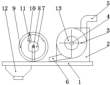
[0034] A self-driven river sand magnetic separator, comprising a platform 1, a magnetic separation device arranged on the platform 1 and a turbine device, the turbine device includes a casing 2, a turbine shaft 4 arranged in the casing 2, a turbine shaft arranged on the turbine The turbine blade 3 on the shaft 4, the river sand inlet 5 arranged on the upper part of the casing 2, the river sand outlet 6 arranged on the lower part of the casing 2, the magnetic separation device includes a drive shaft 8, and the turbine shaft 4 is connected with a generator 13. A motor 7 is connected to the drive shaft 8, and the generator 13 and the motor 7 are connected by wires.
[0035] The magnetic separation device is a disk type magnetic separation device.
[0036] In order to realize automatic collection, the disc-type magnetic separation device includes several permanent magnetic turntables 9 arranged on the drive shaft 8, on which permanent magnet turntables 9 are provided with cleaning...
Embodiment 3
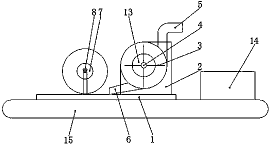
[0040] A self-driven river sand magnetic separator, comprising a platform 1, a magnetic separation device arranged on the platform 1 and a turbine device, the turbine device includes a casing 2, a turbine shaft 4 arranged in the casing 2, a turbine shaft arranged on the turbine The turbine blade 3 on the shaft 4, the river sand inlet 5 arranged on the upper part of the casing 2, the river sand outlet 6 arranged on the lower part of the casing 2, the magnetic separation device includes a drive shaft 8, and the turbine shaft 4 is connected with a generator 13. A motor 7 is connected to the drive shaft 8, and the generator 13 and the motor 7 are connected by wires. A running device is arranged below the platform 1 , and the running device includes a driving mechanism 14 and a running mechanism 15 .
PUM
 Abstract
Description
Claims
Application Information
 - R&D
- Intellectual Property
- Life Sciences
- Materials
- Tech Scout
- Unparalleled Data Quality
- Higher Quality Content
- 60% Fewer Hallucinations
Browse by: Latest US Patents, China's latest patents, Technical Efficacy Thesaurus, Application Domain, Technology Topic, Popular Technical Reports.
© 2025 PatSnap. All rights reserved.Legal|Privacy policy|Modern Slavery Act Transparency Statement|Sitemap|About US| Contact US: help@patsnap.com


