An automatic rotating clamping device for an industrial robot

An industrial robot, automatic rotation technology, applied in the direction of chucks, manipulators, manufacturing tools, etc., can solve the problems of increasing production cost, not applicability, complex automatic rotation of manipulators, etc., to reduce mechanical transmission, improve applicability and work efficiency. , to avoid the effect of multi-joint adjustment and coordination of complex adjustment

Active Publication Date: 2020-10-02
ANHUI POLYTECHNIC UNIV
View PDF9 Cites 0 Cited by
  • Summary
  • Abstract
  • Description
  • Claims
  • Application Information

AI Technical Summary

Problems solved by technology

It can accept human command, and can also run according to pre-programmed programs. Modern industrial robots can also act according to the principles and guidelines formulated by artificial intelligence technology. When performing assembly-line work, the operation of industrial robots on workpieces replaces human labor. The development of productivity has been greatly improved. The existing industrial robots are not completely applicable to the processing of workpieces. Different workpieces require different manipulators to operate. For unique workpieces, a greater degree of design is required. Increased production costs, the automatic rotation of the manipulator is too complicated, so that the rotational torque of the claw arm is too small, and different angle adjustments are required to achieve the applicability of the workpiece. Larger space rotation adjustment

Method used


Image

  • An automatic rotating clamping device for an industrial robot
  • An automatic rotating clamping device for an industrial robot

Examples


Embodiment

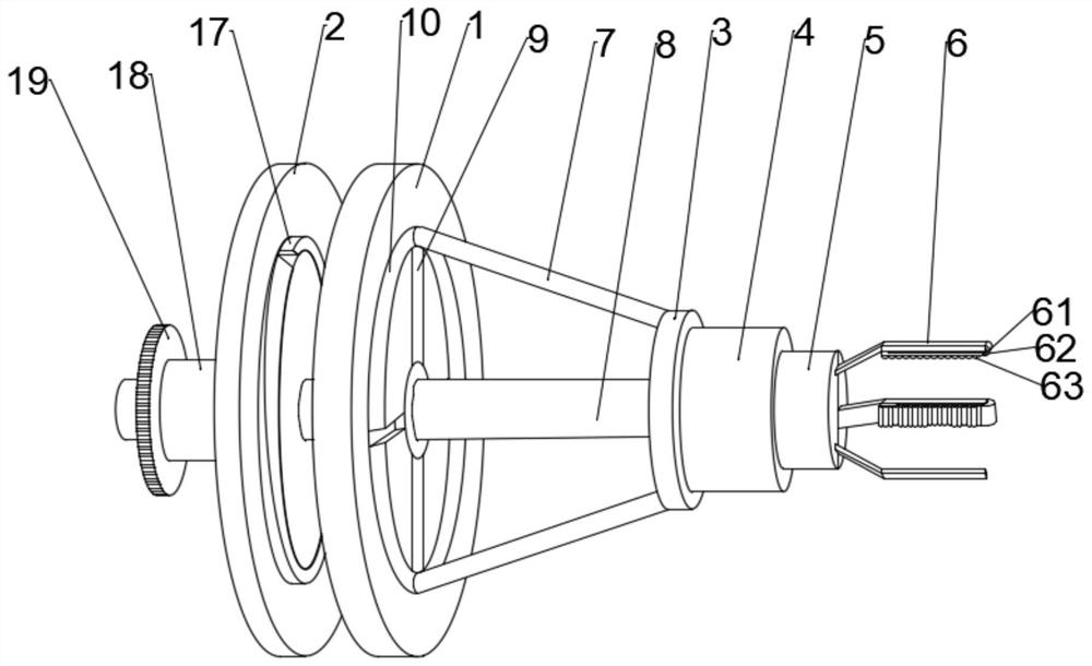
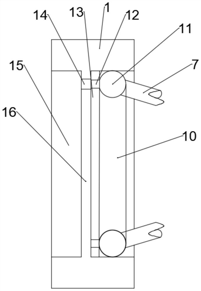
[0021] Such as figure 1 and figure 2 As shown, the present invention provides an automatic rotary clamping device for an industrial robot, comprising a rotary displacement seat 1, an adjusting plate 2, a fixed seat 3 and a main control shaft 8, and the main control shaft 8 passes through the rotary displacement seat transversely 1 and the mobilizing plate 2, the fixed seat 3 is connected with the rotary displacement seat 1 through the connecting rod 7, the end of the main control shaft 8 is fixedly connected to the fixed seat 3, and the right side of the fixed seat 3 is equipped with a rotary hydraulic device 4, The rotary hydraulic device 4 is connected with a rack mechanical driving device 5, and a claw arm 6 is installed on the rack mechanical driving device 5, and an auxiliary micro-motor rotating device 61 is arranged at the end of the claw arm 6, and the micro-motor The rotating device 61 is connected with an auxiliary claw 62, and the surface of the auxiliary claw 62 ...


PUM


Abstract

The invention discloses an automatic rotary clamping device for an industrial robot. The automatic rotary clamping device for the industrial robot comprises a rotary displacement base, a transfer disc, a fixed base and a main control shaft; the main control shaft penetrates through the rotary displacement base and the transfer disc; the fixed base is connected with the rotary displacement base through a connecting rod; the main control shaft is fixedly connected to the fixed base; a revolving hydraulic device is mounted on the fixed base, and is connected with a rack mechanical driving device;a jaw arm is mounted on the rack mechanical driving device; an annular rail and a back ring rail are arranged on two side surfaces of the rotary displacement base separately; a cross displacement rail is arranged in the annular rail; the annular rail is provided with a spherical hinge; the spherical hinge is provided with a limiting slide column; the transfer disc is arranged at the left end of the rotary displacement base; an arc transfer pin is arranged on the right side surface of the transfer disc; a rotary sleeve rod is mounted on the left side surface of the transfer disc; a gear pair sleeves the left end of the rotary sleeve rod; and the rotary sleeve rod sleeves the main control shaft. The automatic rotary clamping device for the industrial robot realizes higher annular torque ofthe industrial robot, precisely assists transverse displacement drive, and improves the applicability and the working efficiency.

Description

technical field [0001] The invention relates to the field of industrial control mechanical equipment, in particular to an automatic rotating clamping device for industrial robots. Background technique [0002] An industrial robot is a multi-joint manipulator or a multi-degree-of-freedom machine device for the industrial field. It can perform work automatically and is a machine that realizes various functions by its own power and control capabilities. It can accept human command, and can also run according to pre-programmed programs. Modern industrial robots can also act according to the principles and guidelines formulated by artificial intelligence technology. When performing assembly-line work, the operation of industrial robots on workpieces replaces human labor. The development of productivity has been greatly improved. The existing industrial robots are not completely applicable to the processing of workpieces. Different workpieces require different manipulators to oper...

Claims


Application Information

Patent Timeline
Patent Type & Authority Patents(China)
IPC IPC(8): B25J9/10B25J15/10
CPCB25J9/102B25J9/106B25J9/109B25J15/10
Inventor 李飞杨国太
Owner ANHUI POLYTECHNIC UNIV
Why Eureka
Try Eureka