Concrete high-efficiency stirring device with cleaning function
What is Al technical title?
Al technical title is built by PatSnap Al team. It summarizes the technical point description of the patent document.
A mixing device and concrete technology, which is applied to cement mixing devices, clay preparation devices, mixer accessories, etc., can solve the problems of poor concrete mixing effect, inconvenient cleaning of inner walls, lack of self-cleaning devices, etc., and achieves ingenious structure and improved mixing. effect, the effect of improving the stirring efficiency
Inactive Publication Date: 2018-10-09
童振奎
View PDF0 Cites 2 Cited by
Summary
Abstract
Description
Claims
Application Information
AI Technical Summary
This helps you quickly interpret patents by identifying the three key elements:
Problems solved by technology
Method used
Benefits of technology
Problems solved by technology
[0003] In the construction process of municipal engineering, concrete is one of the most commonly used construction materials. Before use, the concrete needs to be fully and completely mixed to achieve the uniform mixing effect of sand, gravel and cement in the concrete; the concrete mixing used in the current construction process The mixing effect of the device on concrete is not good, and the mixing efficiency is low. Since the concrete is easy to solidify after drying, it is necessary to clean the inner wall of the mixing device in time after the concrete is discharged. The existing concrete mixing device lacks self-cleaning device, the cleaning of the inner wall is not convenient enough
Method used
Image
Click on the blue label to locate the original text in one second.
Reading with bidirectional positioning of images and text.
Examples
Embodiment Construction
[0019] Below in conjunction with specific embodiment, the technical scheme of this patent is described in further detail:
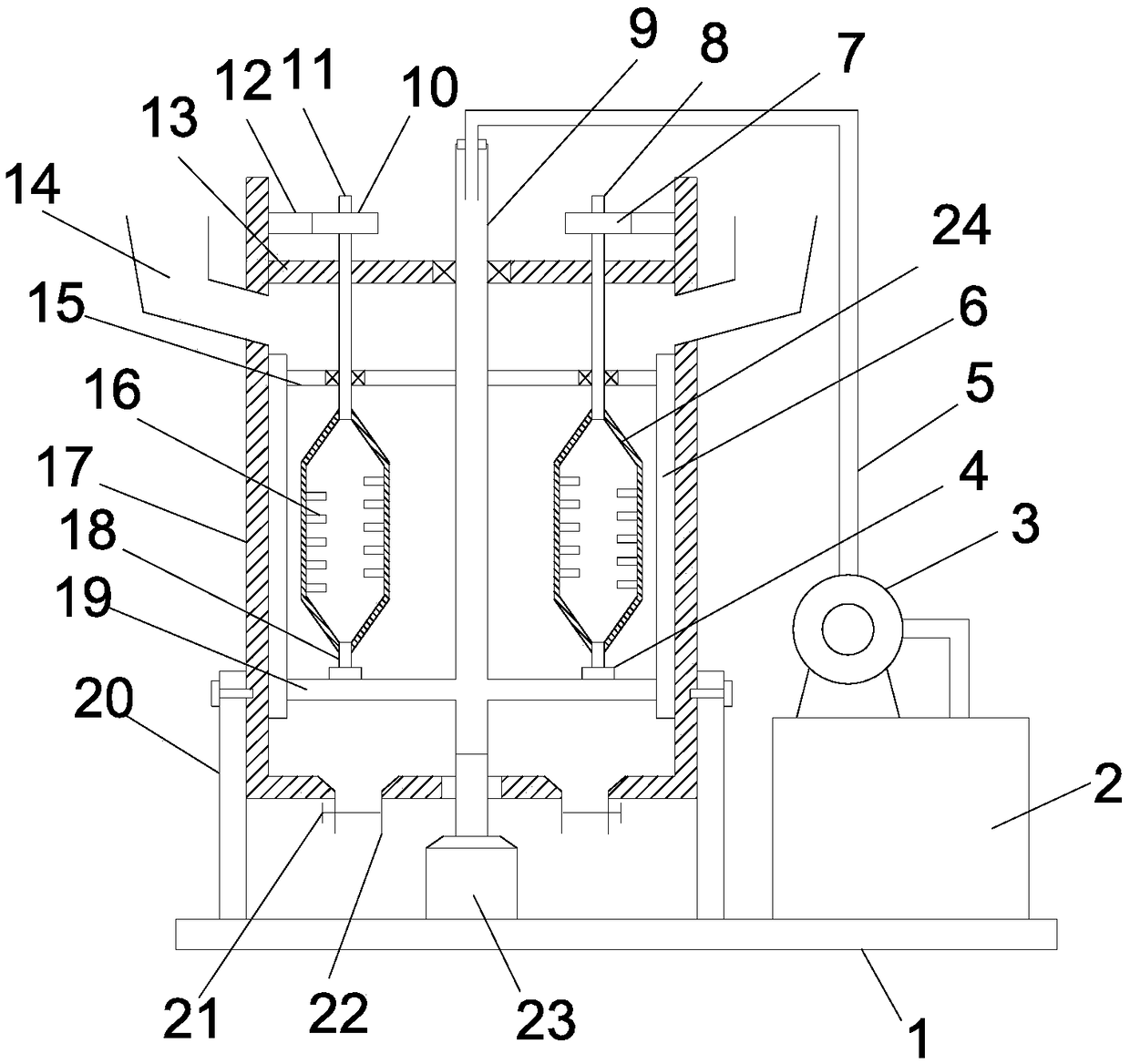
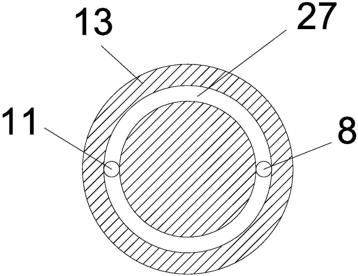
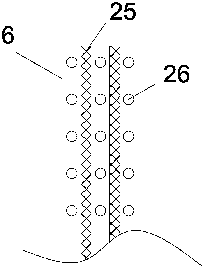
[0020] see Figure 1-4 , a high-efficiency mixing device for concrete with a cleaning function, comprising a base plate 1, a support column 20 is vertically welded and fixedly installed on the base plate 1, a mixing bucket 17 is fixedly supported by the support column 20, and a drive motor 23 is provided on the base plate 1 , the output shaft of the drive motor 23 is coaxially fixed with a drive shaft 9; the drive shaft 9 extends vertically upwards to the inside of the mixing tank 17, the inside of the drive shaft 9 is a hollow structure, and the left and right sides of the drive shaft 9 are symmetrically provided with horizontal Pipe 19, horizontal pipe 19 communicates with drive shaft 9 inside; said drive shaft 9 left and right sides are symmetrically horizontally fixed with connecting rod 15, and the end of connecting rod 15 away from drive shaft 9 is ...
PUM
Abstract
The invention discloses a concrete high-efficiency stirring device with a cleaning function. The concrete high-efficiency stirring device comprises a bottom plate, wherein a support post is verticallywelded and fixedly arranged on the bottom plate; a driving shaft vertically and upwards extends to the inside of a stirring barrel; the inside of the driving shaft is of a hollow structure; horizontal pipes are communicated with the inside of the driving shaft; one end, far away from the driving shaft, of a connecting rod is vertically and fixedly provided with a scraping plate; flexible scrapingstrips are abutted against the inner wall of the stirring barrel; a plurality of spray openings communicated with the inside of the scrapping plate are formed between the flexible scraping strips; aplurality of cutting knife blades are arranged on the side wall of a stirring frame in a staggering way; a water box is arranged on a bottom plate; a conveying pipe connected with the water box through a pipe is arranged on the water box; the outlet end of the conveying pump is communicated with a conveying pipe. The concrete high-efficiency stirring device has the advantages that the structure isingenious; the stirring frame can rotate around a first driven shaft or a second driven shaft; further, the full stirring effect of the stirring frame on concrete in the stirring barrel is achieved;through the cutting knife blades in staggered arrangement, agglomerated concrete is subjected to cutting crushing; the concrete stirring efficiency is improved.
Description
technical field [0001] The invention relates to the technical field of municipal construction machinery, in particular to a high-efficiency concrete mixing device with a cleaning function. Background technique [0002] Municipal engineering refers to the construction of municipal facilities. In my country, municipal facilities refer to various buildings, structures, equipment, etc. that are set up within the planning and construction scope of urban areas, towns (townships), and provide residents with paid or unpaid public products and services based on government responsibilities and obligations. The construction of various public infrastructure supporting urban life belongs to the category of municipal engineering, such as common urban roads, bridges, subways, and various pipelines closely related to life: rainwater, sewage, water supply, reclaimed water, electricity, telecommunications, Heat, gas, etc., as well as the construction of squares, gardens, etc., all belong to ...
Claims
Application Information
Patent Timeline
Application Date:The date an application was filed.
Publication Date:The date a patent or application was officially published.
First Publication Date:The earliest publication date of a patent with the same application number.
Issue Date:Publication date of the patent grant document.
PCT Entry Date:The Entry date of PCT National Phase.
Estimated Expiry Date:The statutory expiry date of a patent right according to the Patent Law, and it is the longest term of protection that the patent right can achieve without the termination of the patent right due to other reasons(Term extension factor has been taken into account ).
Invalid Date:Actual expiry date is based on effective date or publication date of legal transaction data of invalid patent.