
Extruder

A technology for extruders and shells, applied in the field of plastic extrusion equipment, can solve the problems of high labor intensity and prone to errors, and achieve the effects of large heating range, avoiding observation and feeding, and less labor intensity

Inactive Publication Date: 2018-10-09
CHONGQING RUITING PLASTIC
View PDF4 Cites 4 Cited by
  • Summary
  • Abstract
  • Description
  • Claims
  • Application Information

AI Technical Summary

Problems solved by technology

[0005] The purpose of the present invention is to provide an extruder to solve the problem of high labor intensity and prone to mistakes in the prior art

Method used


Image

  • Extruder
  • Extruder

Examples


Embodiment

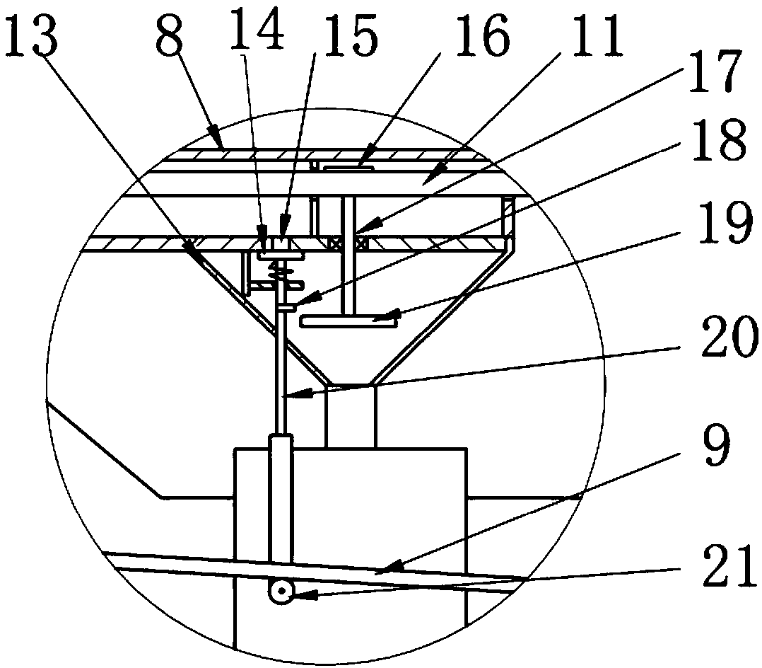
[0020] Embodiment: the extruder in this scheme, as figure 1 and figure 2 As shown, it includes a casing 10 and an elastic telescopic rod 20. The casing 10 is in the shape of a stepped cylinder. The casing 10 is rotatably connected with an active screw 1 for extruding molten plastic. The casing 10 is provided with an auxiliary material adding port. The part of the driving screw 1 outside the housing 10 is coaxially and fixedly connected with a driving gear 4 , and a driven gear 5 is meshed with the driving gear 4 . The driven gear 5 is rotatably connected to the housing 10, and both the driving gear 4 and the driven gear 5 are bevel gears. The driven gear 5 is coaxially and fixedly connected with a rotating shaft 6 , and the shaft side of the rotating shaft 6 is fixedly connected with a driving connecting rod 7 . A driven link 9 is hinged on the active link 7, a heater 12 is hinged on the driven link 9, the heater 12 is slidably connected to the casing 10, and a support roll...


PUM


Abstract

The invention belongs to the field of plastic extrusion equipment and particularly discloses an extruder. The extruder is characterized in that a driving gear is fixedly connected to a driving screw rod; a driven gear is meshed with the driving gear; the driving gear and the driven gear are both bevel gears; a rotating shaft is fixedly connected to the driven gear; a driving connecting rod is fixedly connected to the shaft side of the rotating shaft; a driven connecting rod is hinged to the driving connecting rod; a heater is hinged to the driven connecting rod and is connected to a casing ina sliding manner; a feeding funnel is communicated to the casing; a discharge opening is formed in the feeding funnel; a sealing plate for abutting against and sealing the discharge opening is connected to the inner part of the feeding funnel in a sliding manner; the upper section of an elastic telescopic rod is fixedly connected to the lower part of the sealing plate; a baffle is fixedly connected to the lower section of the elastic telescopic rod and is positioned under the driven connecting rod; a stirring blade for stirring material particles in the feeding funnel is in driving connectionwith the heater. According to the device, the problems of higher labor intensity and easiness in mistakes in the prior art are solved.

Description

technical field [0001] The invention belongs to the field of plastic extrusion equipment, in particular to an extruder. Background technique [0002] The screw refers to a cylinder with a helical groove cut on the outer surface or a cone with a helical groove on the conical surface. Existing extruders often use a screw structure, so that the material gradually changes into a linear motion with the rotation of the screw, and moves toward the machine head, and cooperates with the machine body to compress and generate heat, soften and stir, and mix the materials. [0003] The common screw extruder is a single-screw extruder, and the conveying section and the mixing section are two intermeshing twin-screw extruders. The single-screw extruder relies on the friction generated between the material and the barrel to make the material forward in a way that fills the screw groove. The twin-screw extruder is mainly in a "∞"-shaped barrel. The material in the twin-screw extruder is co...

Claims


Application Information

Patent Timeline
IPC IPC(8): B29C47/10B29C47/78
CPCB29C48/288B29C48/793
Inventor 曹玉毛泽利
Owner CHONGQING RUITING PLASTIC
Learn More