Combined system arranged on pressure-free concealed culvert and used for regulating and controlling suspension mass separation mode according to flow

A combination system and separation method technology, applied in the field of suspension mass separation system, can solve the problems of high investment, flooding and multiple safety of slopes, reduce the amount of support engineering, reduce engineering investment, and ensure safe operation Effect

Pending Publication Date: 2018-10-09
POWERCHINA BEIJING ENG +1
View PDF0 Cites 0 Cited by
  • Summary
  • Abstract
  • Description
  • Claims
  • Application Information

AI Technical Summary

Problems solved by technology

If it is arranged in a conventional way: 1. A large number of high slopes will be generated, which will bring more safety hazards. At the same time, the support of the slopes will also cost a lot of investment; 2. To build a large-scale pool structure, occupying an area of time consuming, large investment
In addition, there are many inconveniences in the operation of separately arranging the structure of the suspended mass separation pool
First of all, according to the size of the structure of the suspended mass separation tank, the optimal working flow rate is basically fixed, with only small fluctuations: when it is in the flood season, the flow rate from the upstream exceeds the optimal working flow rate of the s

Method used


Image

  • Combined system arranged on pressure-free concealed culvert and used for regulating and controlling suspension mass separation mode according to flow

Examples


Embodiment Construction

[0010] Below in conjunction with accompanying drawing and specific embodiment the present invention is described in further detail:

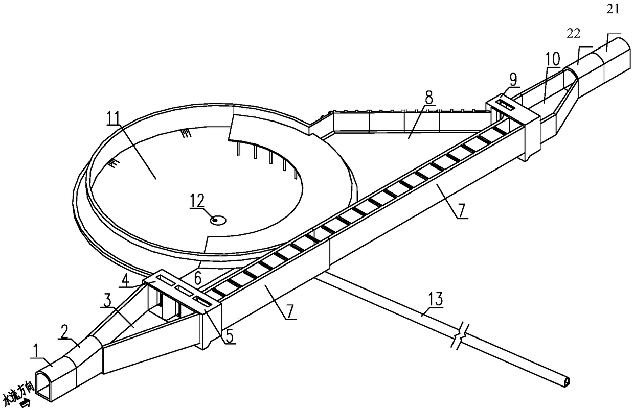
[0011] like figure 1 As shown, the combined system of the present invention, which is arranged on the non-pressure culvert according to flow regulation and suspended mass separation, includes an inlet section, an outlet section and a conical pool section, and an inlet section connected to the non-pressure culvert 1 at the entrance. Diffusion section 3 is arranged, after which the diffusion section is connected to inlet gate 4 and overflow gate 5, after inlet gate 4 is connected to water inlet hole 6, after overflow gate 5 is connected to flow channel 7; overflow pool 8 is arranged at the outlet section, and The overflow tank 8 is arranged side by side with the overflow channel 7, the control gate 9 arranged behind the overflow tank 8 and the overflow channel 7, the tapered section 10 is arranged behind the control gate 9, and the tapered section...


PUM


Abstract

The invention discloses a combined system arranged on a pressure-free buried culvert and used for regulating and controlling the suspension mass separation mode according to flow. The combined systemcomprises an inlet section, an outlet section and a conical water tank section; a diffusion section is arranged at the inlet section which is connected with the part, at the inlet, of the pressure-free buried duct, the rear of diffusion section is then connected with a water inlet gate and the flow through gate, the rear of the water inlet gate is connected with a water inlet hole, and an flow through channel is connected with the rear of the flow through gate; an overflow tank is arranged at the outlet section, the overflow tank and the flow through channel are arranged side by side, a throttling gate is arranged at the rears of the overflow tank and the flow through channel, a gradually-retracting section is arranged at the rear of the throttling gate, and the gradually-retracting section is connected to the part, at the outlet, of the pressure-free buried duct; and the conical water tank section is arranged between the water inlet hole and the overflow tank in a distributed mode, the conical water tank section comprises a conical water pool, wherein a suspension mass discharge bottom hole is formed in the bottom of the conical water pool, a suspension discharge gallery is connected with the suspension discharge bottom hole, the water inlet hole communicates with the conical water tank, and the conical water tank communicates with the overflow tank through an overflow weir. According to the combined system, two parts in the combined system are selected and used according to the flow through amount of the pressure-free buried culvert so that the separation of the suspension mass can be carried out on water flow when the flow amount is large, the water flow can flow through when the flow amount is small, and the operation of a unit can be guaranteed.

Description

technical field [0001] The invention relates to a suspended matter separation system in water conservancy and hydropower projects, in particular to a combined system arranged on a non-pressurized culvert and controlling a suspended matter separation method according to the flow rate. Background technique [0002] Generally, diversion-type hydropower stations built on mountainous rivers or silt-rich rivers often stipulate the maximum allowable particle size and content of suspended matter entering the turbine in order to prevent wear and tear of the turbine. When the water flow for power generation cannot meet the requirements, a suspended mass separation pool structure must be installed. The working principle of the ordinary suspended matter separation tank structure is to reduce the flow velocity of the water flow and reduce the sand-carrying capacity of the water flow by increasing the cross-section of the water, so that the suspended matter larger than the designed minimu...

Claims


Application Information

Patent Timeline
IPC IPC(8): E02B9/00E02B9/04
CPCE02B9/00E02B9/04E02B2201/02Y02E10/20
Inventor 任天卫张红梅杨健关李海冯剑吴奎周利明解红红宋蕊香
Owner POWERCHINA BEIJING ENG
Why Eureka
Try Eureka