Fan speed detection device

A technology of speed detection and fan, applied to devices using electric/magnetic methods, can solve problems such as high cost and complex motor design, and achieve the effects of reducing material costs, simplifying process design, and simple circuit structure

Pending Publication Date: 2018-10-09
SHENZHEN INTELTRON INTELLIGENT SCI & TECH CO LTD
View PDF0 Cites 0 Cited by
  • Summary
  • Abstract
  • Description
  • Claims
  • Application Information

AI Technical Summary

Problems solved by technology

At present, the speed measurement and speed regulation schemes of fans on the market mainly use PG motors, which change the speed of fans by controlling the effective voltage. This design is currently widely used, but there are also shortcomings that cannot be solved by the industry:
[0003] 1. For closed-loop output, an electronic device HALL detection board must be built into the motor
[0004] 2. A magnetic device must be installed around the motor to trigger the hall detection board
[0005] 3. The design of the motor is complex and the cost is high

Method used


Image

  • Fan speed detection device
  • Fan speed detection device
  • Fan speed detection device

Examples


Embodiment Construction

[0013] In order to make those skilled in the art more clearly understand the purpose, technical solutions and advantages of the present invention, the present invention will be further described below in conjunction with the accompanying drawings and embodiments.

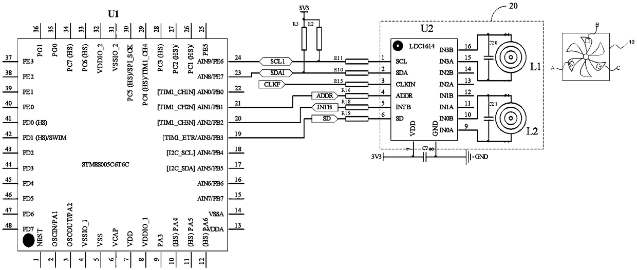
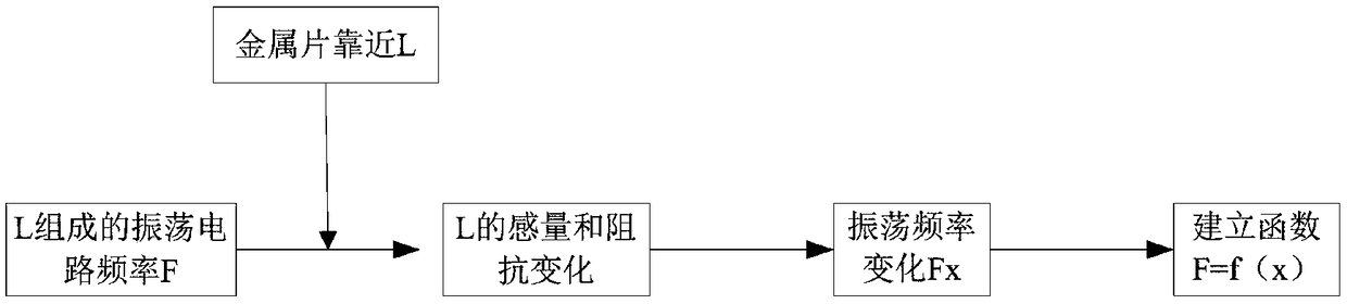
[0014] Such as figure 1 As shown, in one embodiment of the present invention, the fan speed detection device includes a metal sheet disposed on the fan blade of the fan 10, an oscillation circuit module 20 and a logic controller U1. The number of the metal sheets is 3, which are copper foil A, copper foil B and copper foil C respectively. The metal sheets can also be made of other metals or alloys, such as iron, stainless steel, etc. The copper foil A, copper foil Foil B and copper foil C are respectively arranged on three fan blades arranged at 120 degrees.

[0015] The oscillation circuit module 20 includes an induction coil L1, a reference coil L2, a first capacitor C20, a second capacitor C21 and a signal proce...


PUM


Abstract

The invention discloses a fan speed detection device including a metal sheet arranged on blades of a fan, an oscillating circuit module and a logic controller. The oscillating circuit module includesa first oscillating circuit, a second oscillating circuit and a signal processor. The first oscillating circuit includes a first capacitor and an induction ring disposed below vertical projection of blades of the fan. The second oscillating circuit includes a capacitor and a reference ring. The signal processor detects oscillating frequency of the first oscillating circuit and the second oscillating circuit in real time and outputs first oscillating frequency and second oscillating frequency to the logic controller. The logic controller outputs pulse signals according to a comparison result ofthe first oscillating frequency and the second oscillating frequency. The above device does not need to be equipped with a magnetic device and a built-in hall detection device and can realize real time detection of fan speed. The circuit structure is simple, motor material cost is reduced and the cost of a mini-size motor is reduced substantially.

Description

technical field [0001] The invention relates to the technical field of fan speed detection and speed regulation, in particular to a fan speed detection device. Background technique [0002] Now in the field of home appliance applications and industrial control, fans are more and more widely used, ranging from small cooling fans for CPUs to large mine exhaust fans. As a kind of equipment for gas compression and gas transportation, fans must occupy an important role for a considerable period of time. status. At present, the speed measurement and speed regulation schemes of fans on the market mainly use PG motors, which change the speed of fans by controlling the effective voltage. This design is currently widely used, but there are also shortcomings that cannot be solved by the industry: [0003] 1. For closed-loop output, an electronic device HALL detection board must be built into the motor [0004] 2. A magnetic device must be installed around the motor to trigger the hal...

Claims


Application Information

Patent Timeline
Patent Type & Authority Applications(China)
IPC IPC(8): G01P3/44
CPCG01P3/44
Inventor 吴进坤唐波张林董晓勇向杨王义
Owner SHENZHEN INTELTRON INTELLIGENT SCI & TECH CO LTD
Why Eureka
Try Eureka