Three-level DC conversion circuit with controllable neutral point voltage and control method thereof

A neutral point voltage, conversion circuit technology, applied in the direction of controlling generators through magnetic field changes, can solve problems such as aggravating control voltage output harmonics, voltage ripple increase, electromagnetic interference, etc., to improve output voltage quality and reduce voltage. Change rate, effect of reducing switching loss

Pending Publication Date: 2018-10-09
ELECTRIC POWER RES INST OF STATE GRID ZHEJIANG ELECTRIC POWER COMAPNY +1
View PDF0 Cites 3 Cited by
  • Summary
  • Abstract
  • Description
  • Claims
  • Application Information

AI Technical Summary

Problems solved by technology

Since the switching tube in the loop is not an ideal device in practice, there are overlaps of current and voltage waveforms in the turn-on and cut-off processes during use, resulting in switching losses of power devices, which increase with the increase in the corresponding voltage change at both ends during operation. , will reduce the overall system efficiency; at the same time, a higher voltage change rate will also bring more serious electromagnetic interference problems; on the DC output side, a large output voltage level change will also affect the quality of the output voltage, making the voltage ripple Increased, higher common-mode voltage, greater hazards to motor shaft current and insulation
Although some scholars have proposed a three-level chopper circuit based on a double H-bridge, the three-level chopper circuit faces the problem that the neutral point voltage cannot be balanced and controlled, and in practical applications it aggravates the output harmonic of the control voltage. Wave

Method used


Image

  • Three-level DC conversion circuit with controllable neutral point voltage and control method thereof
  • Three-level DC conversion circuit with controllable neutral point voltage and control method thereof
  • Three-level DC conversion circuit with controllable neutral point voltage and control method thereof

Examples


Embodiment Construction

[0066] The present invention will be described in detail below in conjunction with the accompanying drawings and specific embodiments.

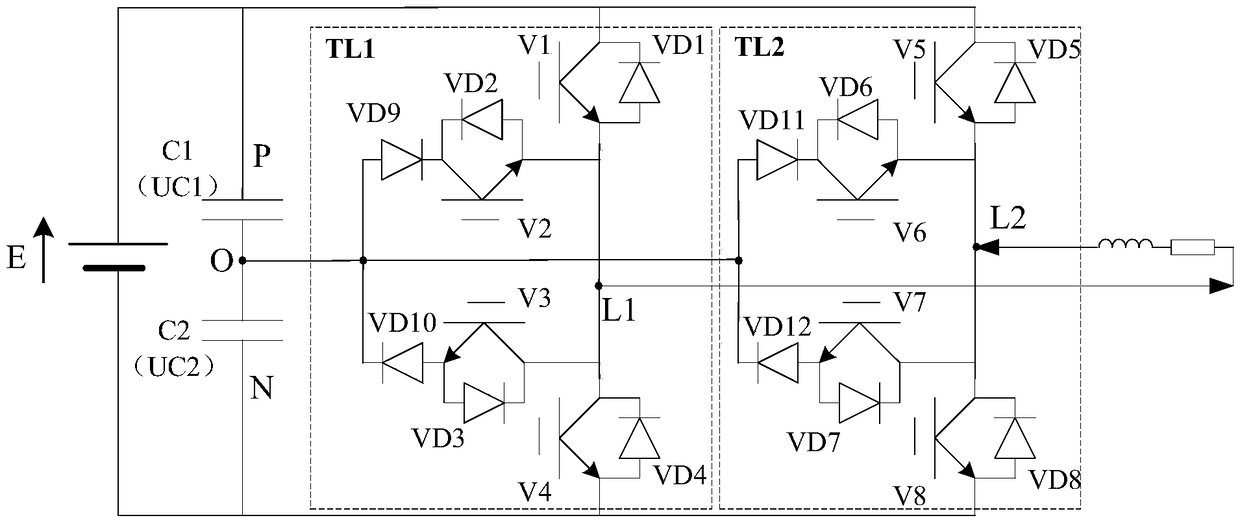
[0067] Such as figure 1 As shown, the present invention provides a three-level DC conversion circuit applied to a flexible excitation system of a generator, including a DC power supply E, a first capacitor C1, a second capacitor C2, a first set of DC chopper circuits TL1 and a second set of DC chopper circuit TL2.

[0068] The first capacitor C1 and the second capacitor C2 are connected in series and parallel to both ends of the DC power supply E, the two ends of the DC power supply E are positive voltage terminal P and negative voltage terminal N respectively, and the connection point between the two capacitors is an intermediate voltage Terminal O.

[0069] The first group of DC chopper circuits TL1 and the second group of DC chopper circuits TL2 are connected in parallel through the positive voltage terminal P, the negative voltage termi...


PUM


Abstract

The invention discloses a three-level DC conversion circuit with controllable neutral point voltage and a control method thereof. The three-level DC conversion circuit of the present invention comprises a DC power supply, a first capacitor, a second capacitor, a first set of DC chopper circuit and a second set of DC chopper circuit; the first set of DC chopper circuit and the second set of DC chopper circuit are connected in parallel by three points of a positive voltage terminal, a negative voltage terminal and an intermediate voltage terminal, and an output positive terminal of the first setof DC chopper circuit and an output negative terminal of the second set of DC chopper circuit are connected in series with a load; and each of the first set of DC chopper circuit and the second set of DC chopper circuit comprises a plurality of switch tubes and a plurality of diodes. The three-level DC conversion circuit of the invention can constitute a plurality of control modes by controllingconduction of the switch tubes, thereby combining a plurality of timing sequence modes, so that four-quadrant voltage control operation of the load condition can be realized, and the purpose of controlling balance of the neutral point voltage of the three-level circuit can be achieved through mode switch.

Description

technical field [0001] The invention belongs to the technical field of flexible excitation systems of generators, in particular to a three-level DC conversion circuit with controllable neutral point voltage and a control method thereof. Background technique [0002] With the large-scale commissioning of UHV DC and flexible DC and the rapid development of new energy power generation with high penetration rate, power electronic power system is in the field of ultra-low frequency power oscillation, sub-synchronous oscillation, millisecond-level reactive power voltage support and other electromagnetic / electromechanical hybrid systems. Increased operational risk in the field. The excitation system is an important part of the synchronous generator, which has an important impact on the safe and stable operation of the power system. Making full use of the regulation ability of the excitation system is one of the most economical and effective means to improve the stability of the pow...

Claims


Application Information

Patent Timeline
Patent Type & Authority Applications(China)
IPC IPC(8): H02P9/36
CPCH02P9/36
Inventor 张建承吴跨宇吴龙韩兵施一峰俞鸿飞卢岑岑熊鸿韬沈轶君房乐李旭段文华卢嘉华赵一琰
Owner ELECTRIC POWER RES INST OF STATE GRID ZHEJIANG ELECTRIC POWER COMAPNY
Why Eureka
Try Eureka