[0018] All the features disclosed in this specification, or all disclosed methods or steps in the process, except for mutually exclusive features and/or steps, can be combined in any manner.
[0019] Any feature disclosed in this specification, unless specifically stated, can be replaced by other equivalent or equivalent alternative features. That is, unless otherwise stated, each feature is just one example of a series of equivalent or similar features.
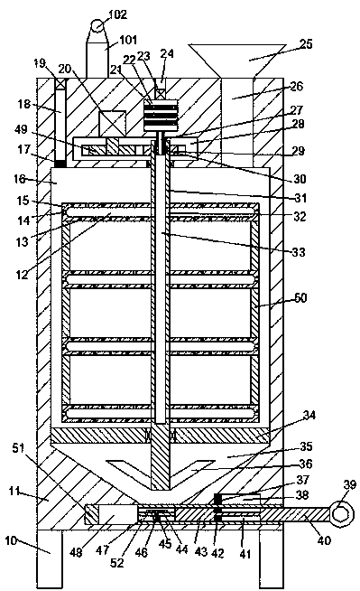
[0020] Such as figure 1 As shown, a high-efficiency drying equipment of the device of the present invention includes a rack 11 fixedly mounted on a bracket 10, a drying cavity 16 is provided in the rack 11, and a bottom wall of the drying cavity 16 is provided with A cone-shaped cavity 35, the bottom of the cone-shaped cavity 35 is provided with a discharge groove communicating with the outside, and the top wall of the drying chamber 16 is provided with a feeding groove 26 and an air outlet groove 18 communicating with the outside, the gas outlet groove A breathable net 17 is fixedly installed at the bottom of 18, an air suction fan 19 is also installed in the air outlet groove 18, a transmission cavity 28 is also provided in the top wall of the drying chamber 16, and the top wall of the transmission cavity 28 is provided with heating A cavity 22, a plurality of heating rods 21 separated up and down and extending laterally in the heating cavity 22, a plurality of vents communicating up and down are provided in the heating rod 21, and a top wall of the heating chamber 22 is provided with an external communication The air inlet groove 24, the air inlet fan 23 is fixedly installed in the air inlet groove 24, the bottom of the drying chamber 16 is fixedly provided with a supporting rod 34, and the center of the supporting rod 34 is rotatably installed with up and down through bearings. An extended central shaft 31. The lower end of the central shaft 31 extends into the conical cavity 35 and is fixedly installed with an inclined rod 36. The upper end of the central shaft 31 penetrates the bottom wall of the transmission cavity 28 and extends into the In the transmission cavity 28, a first gear 29 fixedly connected to the central shaft 31 is provided in the transmission cavity 28, and the left side of the first gear 29 is rotatably mounted with the first gear 29 through a rotating shaft. The meshing second gear 49, the upper end of the rotating shaft is in power connection with the first motor 20 fixedly installed in the top wall of the transmission cavity 28, and the central shaft 31 is provided with a main wind collecting groove 33 with an upward opening, The upper part of the main air gathering groove 33 is rotatably installed with an upwardly extending air duct 27 through a rotating sealing ring 30. The upper end of the air duct 27 penetrates the bottom wall of the heating chamber 22 and communicates with the air duct 27. The drying chamber 16 is symmetrically provided with a stirring arm 15 fixedly connected to the central shaft 31 and distributed up and down. The stirring arm 15 is provided with a laterally extending secondary air gathering tank 12, the secondary air gathering tank 12 The upper and lower end walls are provided with a shunting groove 13 communicating with the drying chamber 16, and an end wall of the secondary air collecting groove 12 away from the central shaft 31 is provided with a dust exhaust hole 14, the secondary air collecting groove 12 and The main wind collecting tank 33 is provided with a communicating groove 32 communicating with each other, a connecting arm 50 is fixedly connected between two agitating arms 15 adjacent to each other up and down, and an opening and closing assembly is also provided at the bottom of the conical cavity 35, The top end surface of the frame 11 is fixedly provided with a lighting device.
[0021] Beneficially or exemplarily, the opening and closing assembly includes a first sliding groove with an opening to the right and transversely passing through the discharge groove, and a sliding plate 51 that can slide left and right is installed in the first sliding groove, so The left end of the sliding plate 51 is provided with a feed trough 48 that communicates up and down, and the right end wall of the feed trough 48 is provided with a second slide trough extending rightward and communicating with the outside, and a top is slidably mounted in the second slide trough. Push plate 40, said jack plate 40 is provided with a mounting groove 47 communicating up and down, said mounting groove 47 is fixedly mounted with a mounting rod 52 extending left and right, and a second motor 46 is fixedly mounted on the lower end of said mounting rod 52 A rotating rod 45 extending up and down is rotatably installed in the mounting rod 52, a fan blade 44 is fixedly installed at the upper end of the rotating rod 45, and the lower end of the rotating rod 45 is power connected with the second motor 46.
[0022] Beneficially or exemplarily, wherein the upper end wall of the first sliding groove is provided with a first limiting groove 38, and the first limiting groove 38 is slidably installed with a second fixed connection with the push plate 51. A limit block 37. When the first limit block 37 abuts against the right end wall of the first limit slot 28, the feed slot 48 is completely communicated with the discharge slot, and the first limit block When 37 abuts against the left end wall of the first limiting groove 28, the feed trough 48 is completely disconnected from the discharge trough.
[0023] Beneficially or exemplarily, wherein the upper and lower end walls of the push plate 43 are symmetrically provided with second limit grooves 41, and the second limit groove 41 is slidably mounted with a fixed connection with the sliding plate 51 The second limiting block 42, when the second limiting block 42 abuts against the left end wall of the second limiting groove 41, the mounting groove 47 is completely retracted in the second sliding groove, and the second limiting When the position block 42 abuts against the right end wall of the second limit groove 41, the installation groove 47 is completely communicated with the discharge groove 48.
[0024] Beneficially or illustratively, a hopper 25 communicating with the feeding trough 26 is fixedly installed on the top surface of the frame 11 to facilitate feeding.
[0025] Beneficially or illustratively, an operating ring 39 is fixedly installed at the right end of the push plate 40 to facilitate the operation of the push plate 40.
[0026] Beneficially or illustratively, the illuminating device includes a fixed lamp holder 101 fixedly arranged on the top end surface of the frame 11, and the top surface of the fixed lamp holder 101 is fixedly provided with an illuminating lamp 102, and the illuminating lamp 102 is connected to a power source. Electrically connected, the lighting device is convenient for night operation of the device.
[0027] When the device of the present invention is in the initial state, the first limiting block 37 abuts against the left end wall of the first limiting groove 28, so that the feeding trough 48 is completely disconnected from the discharging trough, and the second The limiting block 42 abuts against the left end wall of the second limiting slot 41, so that the mounting slot 47 is completely retracted in the second sliding slot, and the first motor 20, the second motor 46, and the intake fan 23 , The suction fan 19 and the heating rod 21 are in the closed state.
[0028] When in use, grain is added to the drying chamber 16 through the hopper 25, and then the first motor 20, the air intake fan 23, the air intake fan 19 and the heating rod 21 are started, and the heating rod 21 generates heat After the heat is generated, the hot air is blown to the main air gathering trough 33 through the air intake fan 23, and then the hot air enters the secondary air gathering trough 12 through the communicating groove 32, and then passes through the branching trough 13 Hot air enters the drying chamber 16, and the first motor 20 can drive the second gear 49 to rotate. The second gear 49 drives the central shaft 31 to rotate through the first gear 29. The central shaft 31 can drive the stirring arm 15 to rotate to stir the grain in the drying cavity 16, thereby accelerating the drying speed of the grain, and the central shaft 31 can drive the inclined rod 36 to the conical cavity The grains in 35 are stirred, so as to prevent grains from accumulating in the cone-shaped cavity 35, and the air suction fan 19 can circulate the air in the drying cavity 16;
[0029] After the grain is dried, the operating ring 39 is used to pull the pushing plate 40 to the right. When the first limiting block 37 abuts against the right end wall of the first limiting groove 28, the material passing groove 48 is in complete communication with the discharging trough, thereby allowing grain to slide downward from the discharging trough. When the grain in the drying chamber 16 has all slipped, the suction fan 19 and the heating rod are turned off 21, and hold the sliding plate 51 and push the push plate 40 to the left, and turn on the second motor 46, when the second limit block 42 and the right end wall of the second limit slot 41 When conflicting, the installation groove 47 is completely communicated with the discharge groove 48. Due to the rotation of the central shaft 31, the dust entering the secondary air gathering groove 12 can be centrifuged and discharged from the dust discharge hole 14. , And the second motor 46 can drive the fan blade 44 to rotate, so that the dust in the drying cavity 16 can fall out of the discharge slot.
[0030] The beneficial effect of the present invention is that: when the device of the present invention is in use, grains are added to the drying cavity through the hopper, and then the first motor, the air intake fan, the air intake fan and the heating rod are started, After the heating rod generates heat, the hot air is blown to the main wind gathering trough through the air intake fan, and then the hot air enters the secondary wind gathering trough through the communication trough, and then passes through the shunt trough Hot air enters the drying chamber, the first motor can drive the second gear to rotate, the second gear drives the central shaft to rotate through the first gear, and the central shaft can drive the The stirring arm rotates to stir the grain in the drying cavity, and the suction fan can circulate the air in the drying cavity, thereby accelerating the grain drying speed;
[0031] The central shaft can drive the inclined rod to stir the grain in the conical cavity, thereby avoiding the accumulation of grain in the conical cavity and improving the drying quality;
[0032] After the grain is dried, the operating ring is used to pull the pusher plate to the right. When the first stop block is against the right end wall of the first stop groove, the feed slot and the outlet The troughs are completely communicated, so that the grains can be allowed to slide downwards from the discharging trough. When the grains in the drying chamber are all slid, turn off the suction fan and heating rod, and press the sliding plate And push the top push plate to the left and turn on the second motor. When the second limit block abuts against the right end wall of the second limit slot, the installation slot and the discharge slot Completely communicated, due to the rotation of the central axis, the dust entering the secondary air gathering groove can be centrifuged and discharged from the dust exhaust hole, and the second motor can drive the fan blade to rotate, thereby Make the dust in the drying chamber fall out of the discharge slot;
[0033] The device of the invention has simple structure, convenient use and good drying quality, thereby increasing the storage period of grain.
[0034] The above shows and describes the basic principles, main features and advantages of the present invention. Those skilled in the industry should understand that the present invention is not limited by the above-mentioned embodiments. The above-mentioned embodiments and the specification describe only the principles of the present invention. Without departing from the spirit and scope of the present invention, the present invention will have various aspects. Various changes and improvements, these changes and improvements fall into the claimed invention. The scope of protection claimed by the present invention is defined by the appended claims and their equivalents.