Composite board automatic gluing and laminating production line

A multi-layer board and production line technology, applied in lamination, layered products, lamination devices, etc., can solve problems such as damage to the surface sprayed with glue, poor lamination, and difficult collection

Inactive Publication Date: 2018-10-12
MAANSHAN JULI SCI & TECH
View PDF0 Cites 9 Cited by
  • Summary
  • Abstract
  • Description
  • Claims
  • Application Information

AI Technical Summary

Problems solved by technology

A relatively important process in the processing of multilayer boards is substrate glue coating, which is to coat the surface of the raw material boards that make up the multilayer board with a layer of insulating glue with uniform thickness to facilitate the bonding between the raw material boards. Using a glue gun to directly spray glue on the surface of the substrate that is continuously conveyed, the glue is difficult to evenly adhere to the surface of the substrate, and the substrate that is continuously conveyed through the conveyor belt is difficult to collect after spraying glue, which will damage the surface sprayed with glue. At the same time, At present, the press used for lamination of multi-layer boards is one-way force application, that is, the driving device drives the upper die to move while the lower die is fixed, or the driving device drives the lower die to move while the upper die is fixed. When the number of layers increases, the Poor pressing due to uneven force

Method used


Image

  • Composite board automatic gluing and laminating production line
  • Composite board automatic gluing and laminating production line
  • Composite board automatic gluing and laminating production line

Examples


Embodiment Construction

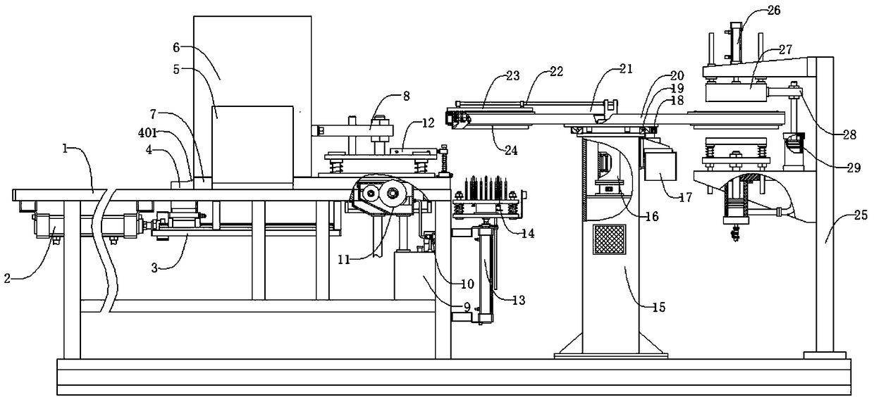
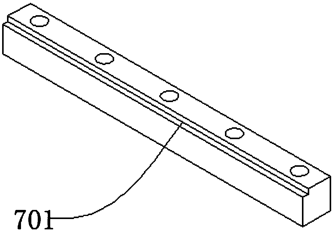
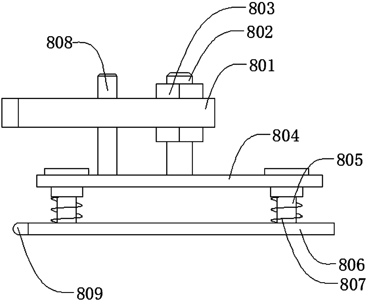
[0028] Such as figure 1 , figure 2 , image 3 , Figure 4 , Figure 5 , Image 6 , Figure 7 , Figure 8 , Figure 9 , Figure 10 , Figure 11As shown, an automatic gluing and pressing production line for multi-layer boards includes a frame 1, a pushing cylinder 2, a lower pallet 3, a pushing head 4, a bracket 5, a board box 6, a carrier strip 7, and a pre-pressing mechanism 8 , glue tank 9, peristaltic pump 10, coating mechanism 11, reclaiming mechanism 12, jacking cylinder 13, carrier plate mechanism 14, column 15, heating mechanism 16, servo motor 17, gear 18, slewing bearing 19, disc heating Box 20, bracket 21, support rod 22, baffle plate 23, material collection mechanism 24, stand 25, press down cylinder 26, upper die 27, connecting arm 28, synchronous lower die mechanism 29, described pushing material cylinder 2 Located at the lower left side of the frame 1, the pusher cylinder 2 is connected to the frame 1 by bolts, the lower supporting plate 3 is located at...


PUM


Abstract

The invention discloses a composite board automatic gluing and laminating production line. The composite board automatic gluing and laminating production line comprises a machine frame, a pushing cylinder, a lower bearing plate, a pushing head, a support, a plate case, a plate bearing strip, a pre-pressing mechanism, a glue box, a peristaltic pump, a coating mechanism, a material taking mechanism,a jacking cylinder, a plate bearing mechanism, a vertical column, a heating mechanism, a servo motor, a gear, a slewing bearing, a round disc heating box, a bearing seat, a supporting rod, a stoppingplate, a material collecting mechanism, a vertical frame, a lower pressing cylinder, an upper die, a connection arm and a synchronous lower die mechanism. The device is simple in structure, can coatthe glue onto the surface of a base plate uniformly, the situation that the glue is not well attached due to secondary pollution can be avoided, the gluing area is accurate, the glue can be recycled,and thus glue waste is effectively avoided. Meanwhile, through floating type design, the upper die and the lower die are laminated simultaneously, uniformity of the lamination is effectively improved,the upper die and the lower die are driven by the single pressing cylinder to laminate, laminating synchronicity is effectively ensured, and the production line can meet the lamination requirement ofbase plates with different layers.

Description

technical field [0001] The invention relates to a mechanical device, in particular to an automatic gluing and pressing production line for multi-layer boards. Background technique [0002] Printed circuit boards, also known as printed circuit boards, are providers of electrical connections for electronic components. They can be divided into single-layer boards and multi-layer boards according to the number of layers. Multi-layer boards are designed for printing due to their high integration and compact structure. The main development direction of the circuit board. A relatively important process in the processing of multilayer boards is substrate glue coating, which is to coat the surface of the raw material boards that make up the multilayer board with a layer of insulating glue with uniform thickness to facilitate the bonding between the raw material boards. Using a glue gun to directly spray glue on the surface of the substrate that is continuously conveyed, the glue is ...

Claims


Application Information

Patent Timeline
Patent Type & Authority Applications(China)
IPC IPC(8): B32B37/06B32B37/10B32B37/12
CPCB32B37/1284B32B37/06B32B37/10
Inventor 史治强
Owner MAANSHAN JULI SCI & TECH
Why Eureka
Try Eureka