Automatic circulation type material bin and control system thereof

An automatic circulation and silo technology, applied in the direction of conveyor control device, object stacking, object destacking, etc., can solve the problem of inability to accurately convey the transmission chain on the pallet, occupying a large space, servo motor or stepping motor output Value accumulation error and other problems, to achieve the effect of increasing the number of pallet tooling, simplifying the structural layout, and compensating for workpiece positioning errors

Active Publication Date: 2018-10-12
NINGXIA KOCEL MACHINE TOOL ACCESSORIES
View PDF6 Cites 1 Cited by
  • Summary
  • Abstract
  • Description
  • Claims
  • Application Information

AI Technical Summary

Problems solved by technology

[0002] Aiming at the workpiece storage silo for machine tool loading and unloading, the technical solutions disclosed in the prior art include: Ningxia Giant Robot System Co., Ltd. applied for the name "CNC Machine Tool Automatic Loading and Unloading Lifting Device", the publication number is CN202240681U, and the public date is 2012.05.30, the device uses a servo motor or stepping motor combined with a pallet position detection device to precisely control the rising position of the pallet, and the motor drives the chain to drive the connecting plate and the pallet to move. Due to the use of chain transmission or toothed belt transmission, the transmission During the transmission process of the chain, with the accumulation of time and transmission length, the output value of the servo motor or stepping motor will produce cumulative errors, and the pallet cannot be accurately

Method used


Image

  • Automatic circulation type material bin and control system thereof
  • Automatic circulation type material bin and control system thereof
  • Automatic circulation type material bin and control system thereof

Examples


Example Embodiment

[0029] The present invention will be described in detail below with reference to the accompanying drawings and several preferred embodiments.
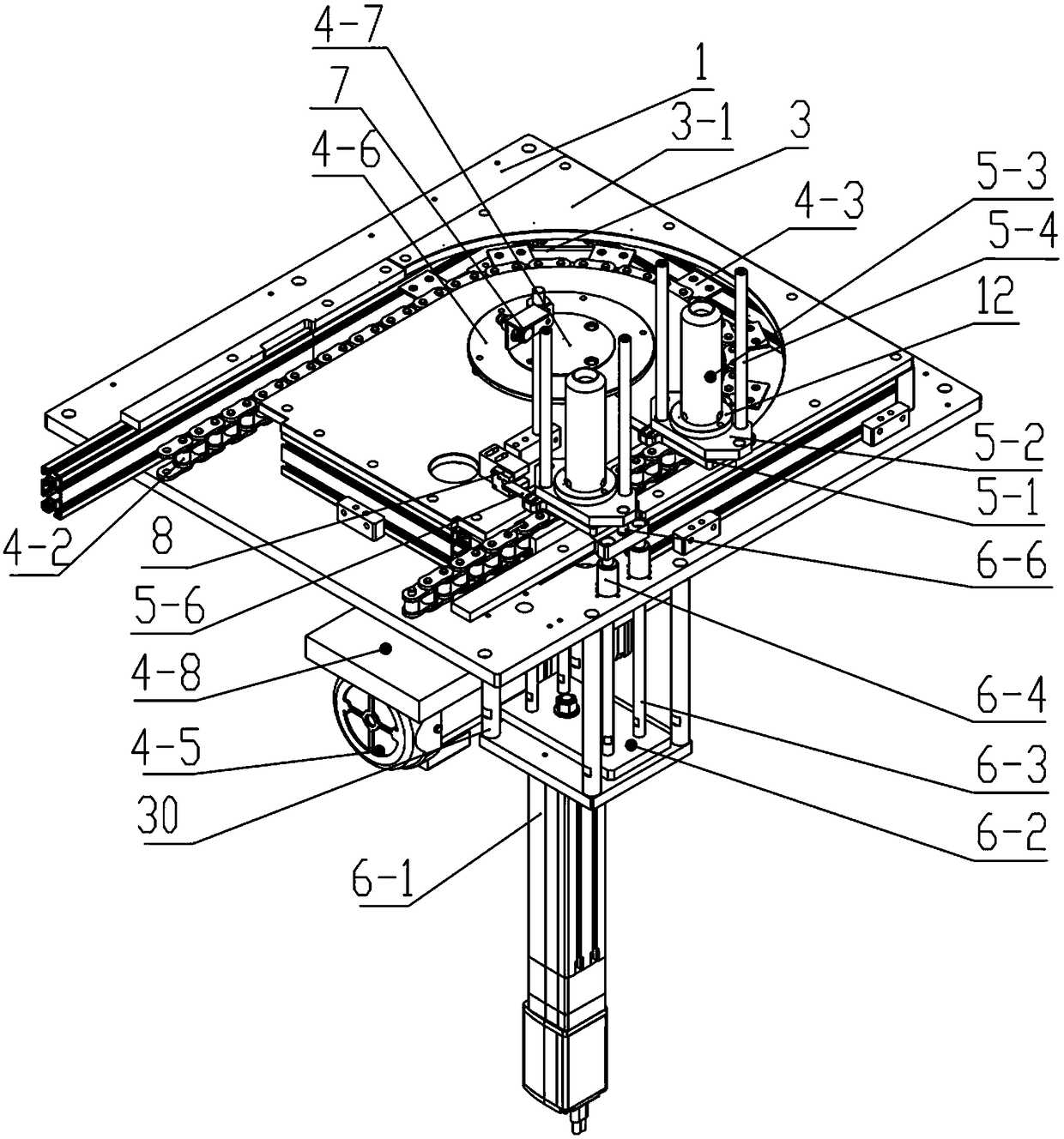
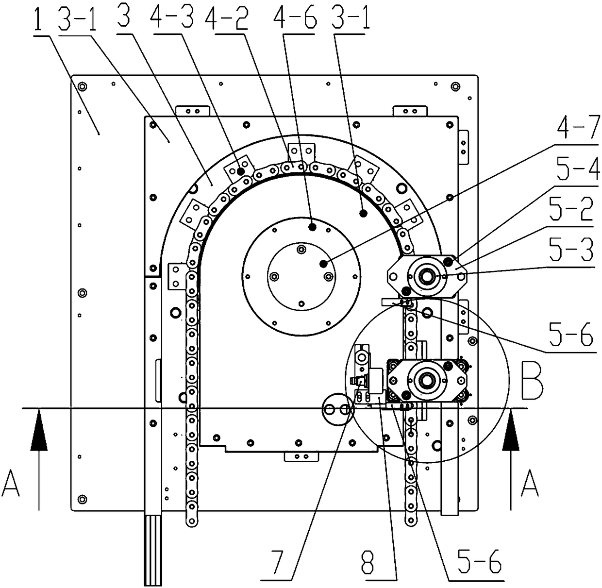
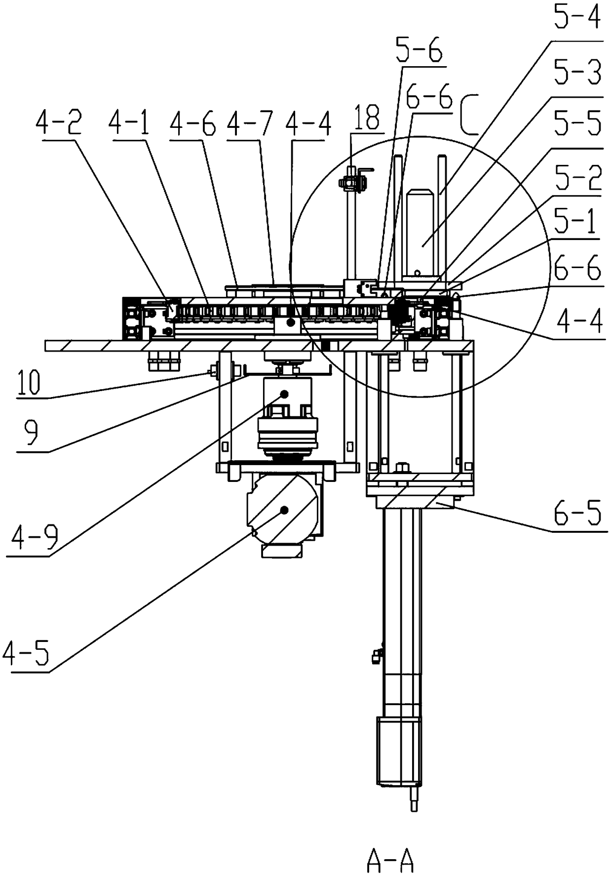
[0030] like Figure 1 to Figure 7As shown in the figure, an automatic circulation silo has a structure comprising: a reference plate 1, which is arranged above the reference plate 1, an annular slideway 3 formed by a metal plate, and a transmission device that is arranged inside the annular slideway 3 and drives along it, The workpiece stacking device that freely slides in the annular slideway 3 is driven by the chain, and the jacking drive device installed under the reference plate 1 and supporting the reference plate is used to lift the workpiece stacking device. The inner ring of the annular track A wear strip 3-1 is laid on the upper end surface of the outer ring and the outer ring. Wherein, the structure of the transmission device includes: a sprocket 4-1 installed on the inner side of the annular slide 3 and located in the cavit...


PUM


Abstract

The invention provides an automatic circulation type material bin. The automatic circulation type material bin solves the technical problem that in the prior art, the device is complex in structure and large in occupied space due to the fact a multi-layer stacking mode is adopted, and the automatic circulation type stock bin mainly and structurally comprises a reference plate, an annular slideway,a transmission device, a workpiece stacking device and a jacking driving device, wherein the annular slideway is arranged on the reference plate and formed by a metal template; the transmission device is arranged on the inner side of the annular slideway and moves along with the annular slideway; the workpiece stacking device is driven to freely slide in the annular slideway by a chain; and the jacking driving device is arranged below the reference plate and is used for supporting the reference plate and jacking the workpiece stacking device. The invention further provides a control system ofthe automatic circulation type material bin. The control system solves the problem that in the prior art, when the device is used for conveying the workpiece stacking device, the output value of a servo motor or a stepping motor can generate accumulative error along with the increase of time and the conveying length, so that a supporting plate cannot be accurately conveyed to the tail end of a transmission chain; and the control system mainly adopts a final position detection mode, so that the accumulative errors are avoided.

Description

technical field [0001] The invention relates to a workpiece storage bin for loading and unloading a machine tool, and belongs to the technical field of mechanical automation. Background technique [0002] Aiming at the workpiece storage silo for machine tool loading and unloading, the technical solutions disclosed in the prior art include: Ningxia Giant Robot System Co., Ltd. applied for the name "CNC Machine Tool Automatic Loading and Unloading Lifting Device", the publication number is CN202240681U, and the public date is 2012.05.30, the device uses a servo motor or stepping motor combined with a pallet position detection device to precisely control the rising position of the pallet, and the motor drives the chain to drive the connecting plate and the pallet to move. Due to the use of chain transmission or toothed belt transmission, the transmission During the transmission process of the chain, with the accumulation of time and transmission length, the output value of the ...

Claims


Application Information

Patent Timeline
IPC IPC(8): B65G1/04B65G43/00B65G61/00
CPCB65G1/04B65G43/00B65G61/00B65G2203/042
Inventor 齐亚文周景吉王宁徐静万文浩虎岩田海瑞毛维刚
Owner NINGXIA KOCEL MACHINE TOOL ACCESSORIES
Why Eureka
Try Eureka