Cloth dyeing device and cloth dyeing method utilizing device

An equipment and technology for dyeing cloth, applied in the field of printing and dyeing, can solve the problems of poor dyeing effect at the crease, prone to discounts, and reduced quality of dyed cloth, so as to achieve better dyeing cloth quality, reduce discounts, and improve the effect of penetration.

Active Publication Date: 2018-10-12
浙江求寔新材料股份有限公司
View PDF9 Cites 2 Cited by
  • Summary
  • Abstract
  • Description
  • Claims
  • Application Information

AI Technical Summary

Problems solved by technology

[0005] Because the fabric needs to reciprocate on the two cloth rolls, it is easy to fold during the winding process. After the fabric is folded, the dyeing effect a

Method used


Image

  • Cloth dyeing device and cloth dyeing method utilizing device
  • Cloth dyeing device and cloth dyeing method utilizing device
  • Cloth dyeing device and cloth dyeing method utilizing device

Examples


Embodiment 1

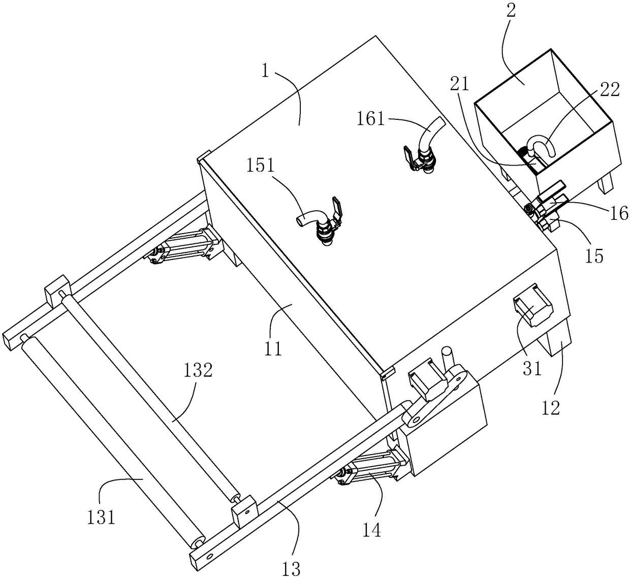
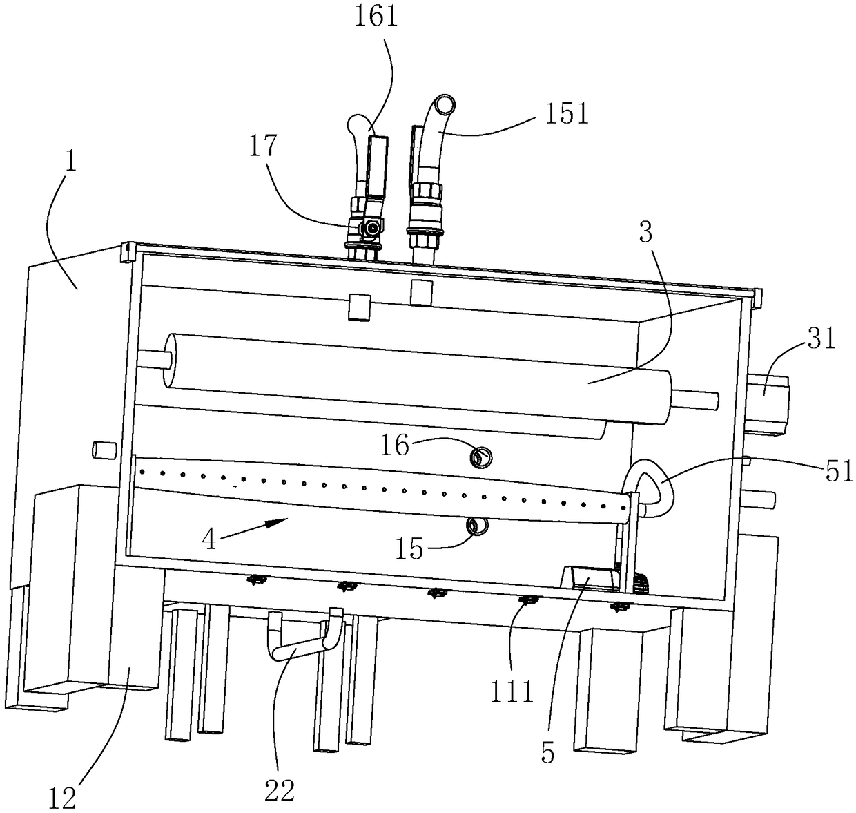
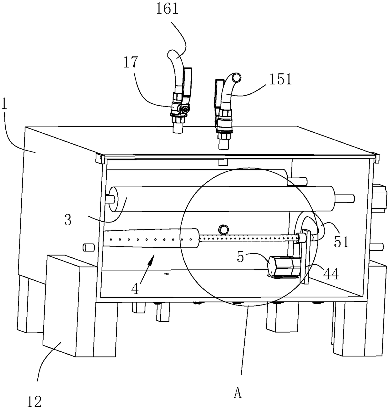
[0054] A kind of cloth dyeing equipment, refer to figure 1 as well as figure 2 , including the main dyeing vat 1 and the secondary dyeing vat 2 connected with the main dyeing vat 1, a pair of cloth rolling rollers 3 are rotatably connected in the main dyeing vat 1, and the main dyeing vat 1 is also fixed with a motor 31 that drives the cloth rolling roller 3 to rotate. A tension roller 4 whose level is lower than that of the cloth rolling roller 3 is rotatably connected, and a number of injection holes 411 respectively facing the two ends of the tension roller 4 run through the side wall of the tension roller 4 .

[0055] A temperature sensor (not shown in the figure) and a pressure sensor (not shown in the figure) are fixed in the main dyeing vat 1, there are two temperature sensors, one is located at the top of the main dyeing vat 1, the other is located at the bottom of the main dyeing vat 1, and the pressure sensor is located at On the top of the main dyeing vat 1, a sti...

Embodiment 2

[0072] A kind of cloth dyeing method utilizing the cloth dyeing equipment of embodiment 1, with reference to Figure 5 , including the following steps:

[0073] S001 cloth feed, details are as follows:

[0074] Put down the swing arm 13, then wind the cloth on the cloth feeding roller 131, open the cylinder cover 11, wind the cloth on the cloth winding roller 3 close to the cloth feeding roller 131, and then take one end of the cloth from the tension roller 4 The bottom passes through and is wound on the cloth roll 3 away from the cloth feed roller 131, and then the cylinder cover 11 is closed to seal.

[0075] S002 dry, as follows:

[0076] Inject high-temperature gas through the high-temperature gas injection pipe 16 until the pressure in the main dyeing vat 1 is 0.2 MPa, then reduce the injection amount of the high-temperature gas injection pipe 16, and discharge the high-temperature gas through the high-temperature gas extraction pipe 161 to maintain a constant pressure ...

Embodiment 3

[0095] The difference from Example 2 is that in S004, after 6 processes of dyeing the cloth, it enters the heat preservation stage and heats it for 4 hours.


PUM


Abstract

The invention relates to the technical field of printing and dyeing and aims to solve the problem that the cloth dyeing quality is reduced due to fabric folding and provide a cloth dyeing device. According to the technical scheme, the cloth dyeing device comprises a main dyeing vat, an auxiliary dyeing vat, a cloth roller and a vat cover and also comprises a tensioning roller, wherein a pluralityof jet holes are formed in the side wall of the tensioning roller and are distributed in two sides of a middle axial point of the tensioning roller, the axial direction of the jet holes obliquely extends towards the axial end of the tensioning roller in the direction deviating from the axis of the tensioning roller, the mouth portions, away from the axis of the tensioning roller, of the jet holesface the end, closest to the jet holes, of the tensioning roller, and a water supply device communicated with the tensioning roller is arranged in the main dyeing vat. The invention also provides a cloth dyeing method. The cloth dyeing method comprises the steps of cloth feeding, drying, cloth dyeing, heat preservation and cloth discharging. Dyeing liquid is jet towards two sides of cloth throughthe jet holes, the power of jetting the dyeing liquid drives the cloth to stretch so as to ensure that the cloth is not folded when being put into the dyeing liquid, the cloth immersion effect of thedyeing liquid is ensured, and the dyeing quality is improved.

Description

technical field [0001] The invention relates to the technical field of printing and dyeing, more specifically, it relates to a cloth dyeing device and a cloth dyeing method using the device. Background technique [0002] The dyeing machine is also called the main dyeing vat and machine vat. Open-width intermittent dyeing equipment is used for dyeing silk, cotton and chemical fiber cloth with small batches and flat appearance, as well as scouring and color fixing before and after dyeing. [0003] The central mechanism of the jigger is two cloth rolls that alternately wind back and forth. The fabric is unwound from one cloth roll and rolled onto the other cloth roll. During the alternate winding process, the fabric passes through the cloth continuously. The dye solution under the roller absorbs the dye solution onto the cloth surface, and absorbs, combines and fixes it during the winding process. [0004] The fabric passes through the dyeing liquid through the tension roller...

Claims


Application Information

Patent Timeline
IPC IPC(8): D06B1/02D06B5/08D06B23/04D06B23/14D06B23/20D06B19/00
CPCD06B1/02D06B5/08D06B19/0029D06B23/04D06B23/14D06B23/20D06B2700/36
Inventor 张伟薛中
Owner 浙江求寔新材料股份有限公司
Why Eureka
Try Eureka