Fall difference type hydroelectric equipment

A power generation equipment and water conservancy technology, which is applied in the field of drop-type hydropower generation equipment, can solve the problems of large power consumption and high cost of pulling wires, and achieve the effect of reducing additional wear

Inactive Publication Date: 2018-10-12
湖州御筵科技有限公司
View PDF0 Cites 0 Cited by
  • Summary
  • Abstract
  • Description
  • Claims
  • Application Information

AI Technical Summary

Problems solved by technology

[0003] In view of this, the present invention provides a drop-type hydroelectric power generation equipment to improve farming in the mountains, but the cost of pulling wires is high, and due to the high altitude, the wires need to be very long, and the loss of wires will also consume a lot of electric energy lack of

Method used


Image

  • Fall difference type hydroelectric equipment
  • Fall difference type hydroelectric equipment
  • Fall difference type hydroelectric equipment

Examples


Embodiment

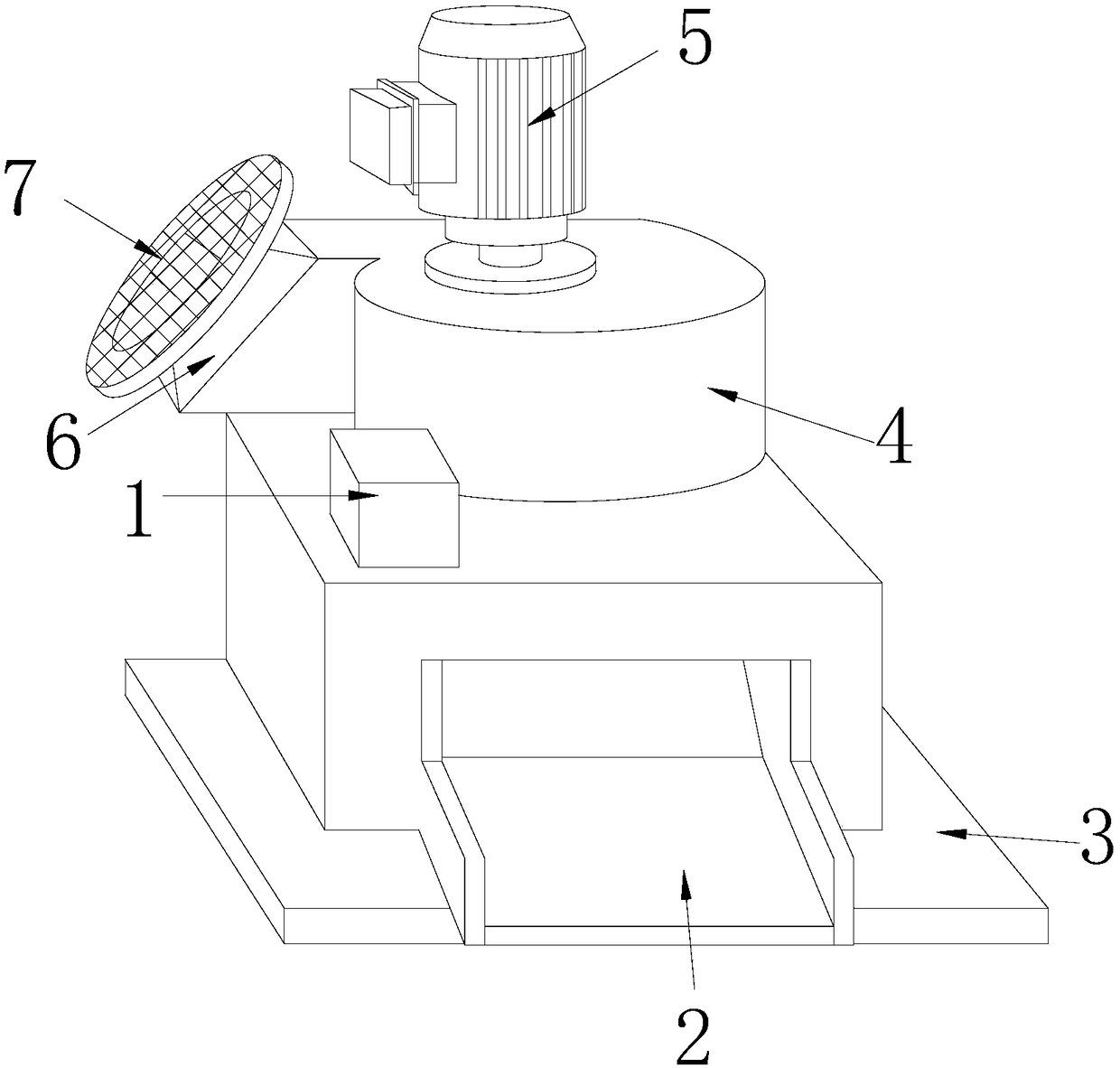
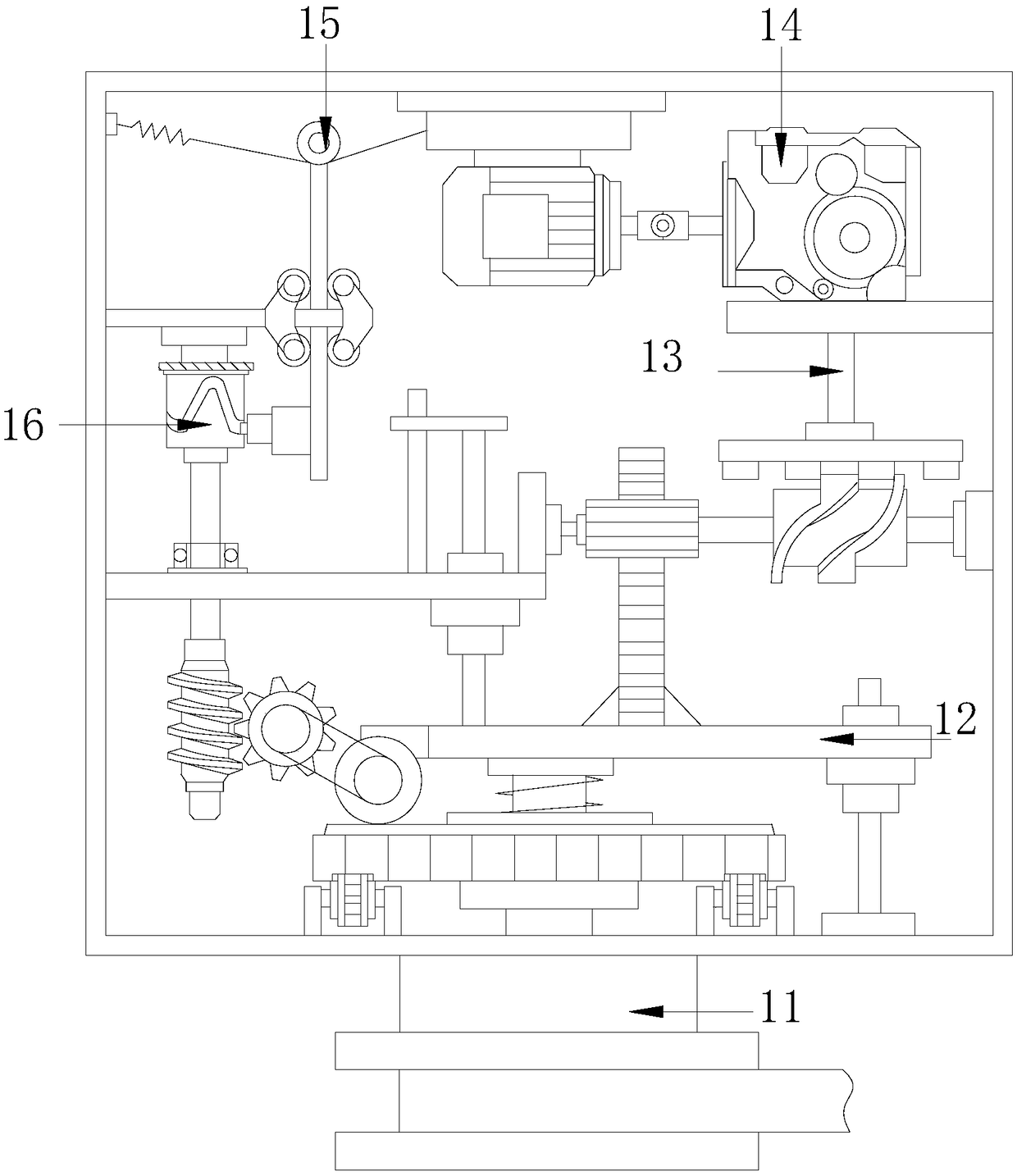
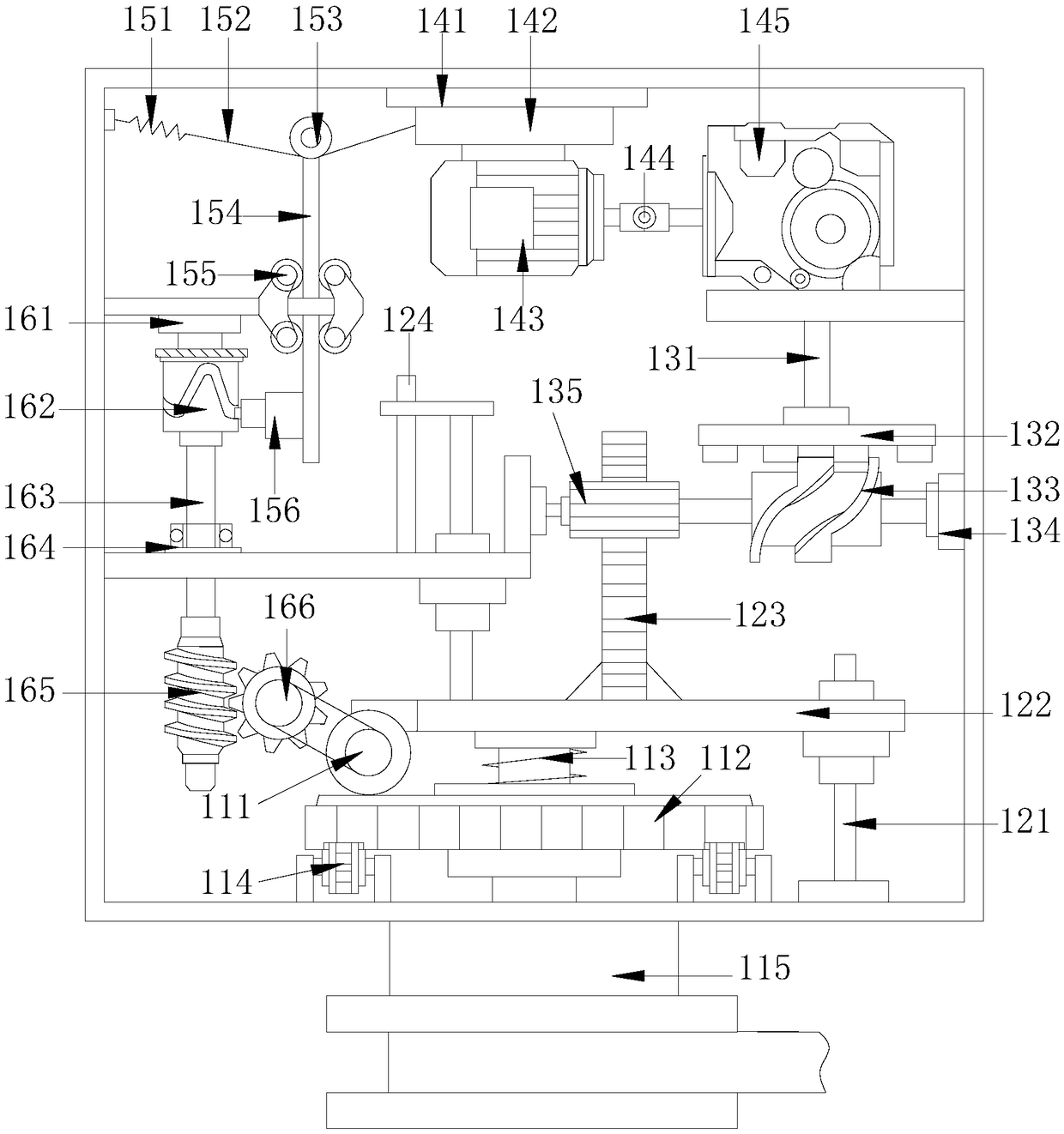
[0020] like Figure 1-Figure 4 As shown, the present invention provides a drop-type hydroelectric power generation equipment, the structure of which includes: a voltage regulator 1, a water flow chamber 2, a base 3, a turbine box 4, a generator 5, a water inlet bucket 6, and a filter screen 7. The bottom of the voltage regulator 1 is fixed on the top of the casing of the water flow chamber 2 by bolts, the water flow chamber 2 is welded and fixed on the top of the base 3 horizontally, and the impeller inside the turbine box 4 is installed on the bottom of the generator 5 , and closely fit with the voltage regulator 1, the water inlet bucket 6 is in interference fit with the filter screen 7 on the top, the water inlet bucket 6 is welded and fixed on the front end of the square groove of the water flow cavity 2, the voltage regulator The device 1 is provided with a detection pulley 11, a movable pressing plate 12, a rotating tooth column 13, a pressing driving device 14, a detect...


PUM


Abstract

The invention discloses fall difference type hydroelectric equipment. The fall difference type hydroelectric equipment structurally comprises a voltage regulator, a water flow cavity, a base, a turbine box, a generator, a water inlet hopper and a filter net. The improved fall difference type hydroelectric equipment is smaller in size and easier to install, a farmer conveniently installs the fall difference type hydroelectric equipment at the fall point of a stream, meanwhile, the power generation efficiency is higher, and the cost problem caused by wire arranging is avoided; by means of the internal voltage regulator, the fall difference type hydroelectric equipment can further stably output electric energy under the severe turbulence; and the rotating speed of the generator is mechanically restrained, while the voltage can be stabilized, the service life of the generator can also be prolonged, and the burning phenomenon caused by a too high rotating speed is avoided.

Description

technical field [0001] The invention is a drop-type hydraulic power generation equipment, which belongs to the field of hydraulic power generation equipment. Background technique [0002] Hydropower generation uses rivers, lakes, etc. to flow water with potential energy from high places to low places, convert the potential energy contained in it into kinetic energy of water turbines, and then use water turbines as the driving force to drive generators to generate electricity. Use hydraulic power (with water head) to drive hydraulic machinery (water turbine) to rotate, and convert water energy into mechanical energy. If another type of machinery (generator) is connected to the water turbine to generate electricity with the rotation of the water turbine, then the mechanical energy is transformed. In a sense, hydropower is the process of converting the potential energy of water into mechanical energy, and then into electrical energy. Many farmers choose to farm on the mountain,...

Claims


Application Information

Patent Timeline
IPC IPC(8): F03B13/00F03B11/00F03B15/00
CPCF03B11/00F03B11/008F03B13/00F03B15/00Y02E10/20
Inventor 杨勇强
Owner 湖州御筵科技有限公司
Why Eureka
Try Eureka